Signetics 2650 & 2636 programming/Printable version
| This is the print version of Signetics 2650 & 2636 programming You won't see this message or any elements not part of the book's content when you print or preview this page. |
Introduction
edit- Acetronic MPU 1000/2000

- Audiosonic PP-1292/1392 Advanced Programmable Video System

- Aureac Tele Computer

- Fountain Force 2

- Fountain 1292/1392 Advanced Programmable Video System
- Grandstand Advanced Programmable Video System
- Grundig Super Play Computer 4000

- Hanimex HMG 1292/1392 Advanced Programmable Video System

- Interton VC 4000
- ITMC Vidéo Ordinateur MPT-05

- Karvan Jeu Video TV
- Lansay 1392
- Palson CX-3000 Data Bass Sistem
- Prinztronic VC-6000
- Radofin 1292/1392 Advanced Programmable Video System
- Rowtron Television Computer System
- Societe Occitane Electronique OC-2000
- Teleng Television Computer System
- TRQ Video Computer H-21
- Videomaster Database
- Voltmace Database
Note: Flags indicate primary country of the company. Many consoles were available in multiple countries.
This book is a guide to programming a family of video game consoles based on the Signetics 2650 microprocessor and 2636 Programmable Video Interface. These consoles were manufactured and marketed in the late 1970s and early 1980s by numerous companies in Europe, Australia and New Zealand. They are largely software-compatible, though there are physical differences in the games cartridges. Some of the joysticks are self-centering while others are not. The audio effects and colour circuitry also vary slightly between clones.
This book will initially concentrate on the Videomaster / Voltmace Database, as that is the console I have to work with. When differences are documented from reliable sources, they will be discussed here where appropriate. I stress reliable as there seems to be a lot of badly sourced misinformation about these consoles on the web.
-
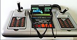
 Videomaster Database
 -
 Interton VC 4000
 -
 Acetronic MPU 1000


Readers should have some basic knowledge of assembler level programming, perhaps with processors of a similar vintage such as the 6502 or Z80. A little background in digital and analogue electronics would be helpful too. The glossary and bibliography will include basic information and links to further reading to fill in gaps in knowledge concerning these fundamentals.
This book starts with a description of the hardware of the console, and information about the microprocessor and programmable video interface. The intent is to keep these sections concise yet detailed so that they serve as a handy reference for programmers. This is followed by a series of tutorials showing how to program the various elements of the console so that eventually the reader will have enough knowledge to build their own games. Code for these tutorials will be found in the appendices. It is intended that this code will not only make it easy for the reader to gain hands-on experience, but will also provide useful chunks of code that can be built upon to create more useful programs. A second set of tutorials will delve further into code that combines these basic elements into something more interactive.
My objective in starting this book is to encourage the creation of new games for these consoles.
-
 ITMC MPT-05
 -
 Société Occitane d'électronique OC 2000
 -
 Grundig Super Play Computer 4000


Console Hardware
editExternally these consoles are very similar to one another apart from their styling. They all have a slot for the game cartridge, four switches on the front, a pair of hand-controllers, and leads for power input and connection to a TV. Some have external power packs that supply low voltages to the console from the mains, while others perform this function internally.
The four switches on the console are power on/off, reset/load, start and select. (The load label that appears on some machines has led to some misinformation appearing on the web, as it has given the impression that the game is loaded from the cartridge to internal memory. This is incorrect as there is no internal memory on these machines. That button simply forces the microprocessor to start executing the program at memory address $0000 in the cartridge.)
Some of the consoles, such as the Database, have all the electronics on one printed circuit board, while others such as the Interton have divided the circuit into modules housed on smaller boards.
The game cartridge was configured in several different formats. Most had either a 2k or a 4k ROM, while some were 6k ROM and some had 1k RAM. The Acetronic Hobby Module was 2k ROM and 2k RAM.
System architecture
edit
This block diagram shows the main components of the console and their most significant interconnections:
Clock generation
editAll the necessary clocks for the system are derived from a single 8.867238 MHz crystal connected to the the video encoder. The encoder uses this for generating colour signals in its composite video output. It also divides it by 2½ to give a 3.55 MHz clock for the 2621 sync generator.
The sync generator passes this to the 2636 PVI as a pixel (or position) clock, and divides it by four to clock the microprocessor at 887 kHz. It also generates the vertical and horizontal reset signals for the PVI, as well as composite video timing signals for the video encoder.
Processor
editThe Signetics 2650 is an eight bit microprocessor capable of addressing 32kB of memory. However, in this console only 13 of its address lines are used to access up to 8kB of memory.
The Reset signal causes it to start executing code at address $0000.
An Interrupt signal from the PVI, in conjunction with a vector supplied by the PVI, can cause execution to temporarily switch to $0003.
The Sense input is used to detect the state of the VRST signal (vertical blanking). The Flag output is used to determine which of the joystick potentiometers are connected to the PVI.
Memory map
edit2636 PVI
editThe 2636 Programmable Video Interface has 108 registers that control its audio and video output. Four other registers provide the processor with information about video object collisions and analogue joystick data. A further 37 registers are available as general purpose memory locations.
The PVI also generates chip select signals for various interface circuits and memory in the games cartridge. It also sends and interrupt request signal to the processor when it needs attention. See 2636 PVI for more details.
Effects
editThe PVI can only generate a single square wave frequency. This is fed to some audio effects circuits that are controlled from the microprocessor via the 74LS378 latches. These circuits:
- turn the PVI audio on/off
- turn on white noise
- cause an explosion sound
- set one of four volume levels
One other bit in the effects register can invert the colour of the background grid and screen.

Player inputs
editThe Reset button on the console causes the processor to start executing the program at memory address $0000 in the game cartridge.
The Start, Select and keypad buttons are all controlled by the 74LS258 and 74LS156. They are arranged as a matrix, with the '156 selecting the column, and the '258 reading the data from the rows.
Each joystick controls two variable resistors. The four variable resistors are connected to the two analogue-to-digital converter inputs on the PVI via the CD4053 analogue multiplexer. The Flag output from the microprocessor controls which two resistors are to be measured.
Programmers should note that the joysticks are self-centring on some consoles and not on others. This can have a big impact on how they are used and programmed.
2650 processor
edit
The 2650 was first released by Signetics in 1975.[1] These video game consoles use the 2650A, a redesigned version that was smaller, cheaper to manufacture and had improved operating margins. The 2650A was released in 1977.[2] A later version, the 2650B, had a few design changes and additional features, but we aren't concerned with those here. The 2650 was fabricated in NMOS, was TTL compatible, and its many control signals made it simple to interface to. It was described by Adam Osborne as being a very minicomputer-like device having been closely based on the IBM 1130. It has a number of distinguishing features:
- 32k byte address range, organised as four 8k byte pages.
- Variable-length instructions of 1, 2 or 3 bytes.
- Single bit I/O path (flag and sense pins).
- Multiple addressing modes including indirect and indexed.
- Vectored interrupt.
- Eight-level return address stack.
- Seven 8-bit registers.
- Two program status bytes.
- Powerful instruction set.
Registers
editThe 2650 has seven general purpose 8-bit registers. R0 is always available, whereas there are two banks of R1, R2 and R3 which are selected by the RS bit in the Program Status Word.
Program Status Word
editThe Program Status Word (PSW) is a special purpose register that contains status and control bits. It is divided into two bytes, the Program Status Upper (PSU) and Program Status Lower (PSL). The PSW bits may be tested, loaded, stored, preset or cleared using the instructions tpsu, tpsl, lpsu, lpsl, spsu, spsl, ppsu, ppsl, cpsu or cpsl.
|
| ||||||||||||||||||||||||||||||||||
| |||||||||||||||||||||||||||||||||||
Reset
editWhen a Reset pulse is applied to the 2650A, program execution is forced to begin at memory address 0. The only other thing we know for sure about the state of the processor after reset is that the Interrupt Inhibit bit in the Program Status Word is cleared. As we very much don’t want spontaneous interrupts to happen, one of the first things our program should do is set it to disable them until we ready for them. The “Signetics 2650 Initialization Application Memo” also suggests that we may set the Stack Pointer to zero, and that we should set the Register Select bit to a known state.[5]
The With Carry bit and the Compare bit may be set to whatever condition you will need them in first. In a simple program which has them in the same state throughout, this is a straightforward decision. In more complex programs it is generally best to set them to the most used condition initially, and then switch them back and forth whenever the opposite condition is needed. If the With Carry bit is on, then the Carry bit should be initialised appropriately before the first arithmetic instruction. Otherwise there is no need to initialise Carry or any of the other bits (Condition Code, Interdigit Carry, or Overflow). [5]
Interrupts
editCertain events occurring in the PVI cause it to signal the 2650 that it needs attention by setting the interrupt line low. If the Interrupt Inhibit bit in the Program Status Word is not set, (in other words interrupts are enabled), the processor will finish the current instruction and then set the Interrupt Inhibit bit. The PVI then outputs its interrupt vector, 3, to the data bus and the processor executes a ZBSR (branch to subroutine on page zero) to address $0003.
When the interrupt service subroutine has finished, it should be exited with either a RETC or RETE instruction. The latter will re-enable interrupts.
Instruction set
editAll mnemonics in the 2650A instruction set are 3 or 4 characters long. The first two or three characters specify the operation, and if present, a final character indicates an addressing mode to use (see the next section, Addressing modes for more detail). Assembly code for the 2650 generally looks something like this:
loop:   lodi,r0 $20          ; load r0 from the byte immediately following, $20
        stra,r0 $1F40	     ; store r0 in the absolute address $1F40
        eorz    r0           ; exclusive-or r0 with itself
        bctr,un loop         ; branch relative, unconditionally, to address specified by 'loop'
There are 34 basic instructions:
| Transfer | LOD | Z,I,R,A | Load register |
| STR | Z,R,A | Store register | |
| Arithmetic | ADD | Z,I,R,A | Add to register |
| SUB | Z,I,R,A | Subtract from register | |
| DAR | Decimal adjust register | ||
| Logical | AND | Z,I,R,A | Bitwise AND to register |
| IOR | Z,I,R,A | Bitwise OR to register | |
| EOR | Z,I,R,A | Bitwise EXCLUSIVE-OR to register | |
| Test | COM | Z,I,R,A | Compare value to register |
| TM | I | Test masked bits of register | |
| Rotate | RRR | Rotate register right by one bit | |
| RRL | Rotate register left by one bit | ||
| Branch | BCT | R,A | Branch on condition true |
| BCF | R,A | Branch on condition false | |
| BRN | R,A | Branch if register not-zero | |
| BIR | R,A | Increment the register and branch if it is not zero | |
| BDR | R,A | Decrement the register and branch if it is not zero | |
| ZBR | R | Branch, relative to address $0000 | |
| BX | A | Branch, indexed | |
| Call / Return | BST | R,A | Branch to subroutine on condition true |
| BSF | R,A | Branch to subroutine on condition false | |
| BSN | R,A | Branch to subroutine if register not-zero | |
| ZBS | R | Branch to subroutine, relative to address $0000 | |
| BSX | A | Branch to subroutine, indexed | |
| RET | C,E | Conditionally return from subroutine. RETE also enables interrupts | |
| Input / Output | WRT | C,D,E | Input/output hardware is not implemented on these consoles |
| RED | C,D,E | ||
| Miscellaneous | HALT | Enter WAIT state until processor is reset or interrupted | |
| NOP | Do nothing except fetch and execute this instruction | ||
| Program status word | LPS | U,L | Load the PSW |
| SPS | U,L | Store the PSW | |
| CPS | U,L | Clear specified bits in the the PSW | |
| PPS | U,L | Preset specified bits in the the PSW | |
| TPS | U,L | Test specified bits in the the PSW |
Addressing modes
editThe Signetics 2650 has four main addressing modes: Register, Immediate, Relative and Absolute. In addition Indirect and Indexing may be combined with some of these.
Register addressing
editAll register-to-register instructions are 1 byte in length and use R0 as the first operand, while the other can be any of R0, R1, R2, R3.
        lodz    r3          ; load r0 from r3
        addz    r2          ; r0 = r0 + r2
        lodz    r0          ; not very useful!
        eorz    r0          ; exclusive-or r0 with itself
                            ; very useful! A one byte instruction for r0 = 0
Immediate addressing
editIn immediate addressing the first operand, which can be any register, is specified next to the instruction; followed by the value of the other operand, which implicitly must be a constant. All immediate addressing instructions are two bytes in length.
        lodi,r2 $20        ; r2 = 32
        subi,r0 8	   ; r0 = r0 - 8
        iori,r1 %00100000  ; set bit5 of r1
        comi,r3 15         ; compare r0 to 15
Absolute addressing
editIn absolute addressing the first operand, which can be any register(but see exception in Indexed addressing below), is specified next to the instruction. The second argument designates the absolute address of the memory location where the other operand is located.
Relative addressing
editIn relative addressing the first operand, which can be any register, is specified next to the instruction. The second argument designates a memory location where the other operand is located. This second argument is a relative displacement from the current address and can be any value from -64 to +63. In practice we don't specify this value as a number. It generally takes the form of a label and the assembler does the calculation for us. If the label is too far away the assembler will generate an error message. Relative addressing is also used in branch instructions to jump to a memory location close by.
        lodr,r2 number     ; r2 = 42
        bctr,un next       ; branch to next
number: db      42         ; define a data byte = 42
next:   addi,r2 53
Indexed addressing
editWhen indexed addressing is used, the effective address is calculated by adding the contents of the specified index register to the address field. The addition uses the value in the index register as an 8-bit positive number.
        lodi,r2 5
        loda,r0 $1F00,r2    ; r0 = contents of address $1F05
Note that the first argument is always r0. Some assemblers may allow this to be omitted from the code, but for the sake of readability it should be included if possible.
Two other options allow for the index register to be auto-decremented or auto-incremented before it is added to the base address:
        lodi,r2 5
        loda,r0 $1F00,r2+    ; r0 = contents of address $1F06
        lodi,r3 $A6
        loda,r0 $1000,r3-    ; r0 = contents of address $10A5
Indexing may only be used with absolute addressing. It may not be used with branch instructions, but two special instructions exist for this purpose. They are BXA (branch indexed, absolute) and BSXA (branch to subroutine indexed, absolute). Auto-increment and auto-decrement cannot be used with them, and register R3 must be specified as the index register.
Indirect addressing
editIndirect addressing means that the argument address of an instruction is not specified by the instruction itself, but rather the argument address will be found in the two bytes pointed to by the instruction. The indirect addressing mode is indicated by an asterisk.
pointer dw $0F00            ; in most cases this would be an address in RAM, i.e. a variable
        .....
        loda,r1 *pointer    ; r1 = contents of $0F00
Indirection may be used with relative addressing as well, but since code in these consoles is operating out of ROM, and RAM addresses are generally too far away for a relative address, there is no apparent use. One exception does occur when space for code is at a premium:
              :bar   equ     $1F0E
0000  066A    :      lodi,r2 $6A
0002  CE1F0E  :      stra,r2 bar
0005  0D1F0E  :foo   loda,r1 bar
0008  0BFC    :      lodr,r3 *foo+1   ; load r3 indirectly from $0006, i.e. $1F0E
The last two instructions both load a register from bar, but the last instruction only uses two bytes rather than three.
Indexed Indirect addressing
editWhen indexing and indirect are used together, the value of the index register is added to the indirect address, not to the value in the address field of the instruction.
Further reading
editFor more detailed information consult the Signetics 2650 User Manual, available as a full pdf or abridged for programmers as html.
References
edit- ↑ Microcomputer Digest (PDF). Cupertino, CA: Microcomputer Associates Inc. 2 (1): 1–3. July 1975 http://bitsavers.trailing-edge.com/magazines/Microcomputer_Digest/Microcomputer_Digest_v02n01_Jul75.pdf. Archived (PDF) from the original on 1 February 2014. Retrieved 4 December 2021.
{{cite journal}}: Cite has empty unknown parameter:|1=(help); Invalid|url-access=4 December 2021(help); Missing or empty|title=(help) - ↑ "Signetics 2650: An IBM on a Chip". The CPUshack museum. October 16th, 2016. Retrieved 5 December 2021.
{{cite web}}: Check date values in:|date=(help) - ↑ Osborne, Adam (1978). An introduction to microcomputers (PDF). Berkeley, Calif.: Osborne & Associates. p. 736. ISBN 0-931988-15-2. Retrieved 4 November 2021.
- ↑ 2650 Series Microprocessor datasheet (PDF). Philips. Retrieved 4 November 2021.
- ↑ a b Signetics Applications Memo MP51 - 2650 initialization (PDF). Philips. Retrieved 4 November 2021.
2636 PVI
editThis section of the book is primarily reference material for the PVI. More detailed discussions can be found in the Tutorials. |
The Signetics 2636 Programmable Video Interface (PVI) is a 40-pin DIL chip that handles a number of functions within the console:
- Video generation
- Screen colour
- Background grid
- Score digits
- Four objects (sprites)
- Object completion and collision detection
- Square wave audio
- A/D conversion for the analogue joysticks
- Chip select signals for memory and input/output devices
- 37 bytes of scratch memory
These functions are all implemented by reading and writing to various registers within the PVI.
 |
Screen colour
Score digits Objects Background grid Object duplicates |
PVI registers
editInternally the PVI registers are located at addresses $F00 to $FFF. Within the console's memory map they are located at addresses $1F00 to $1FFF. Programmers only need to be concerned with these latter addresses, so those will be the ones we use throughout this book. For the same reason we will also ignore the areas where the memory map is duplicated.
Note that some control registers are write-only. If a program needs to know the contents of any of them, a duplicate copy must be saved elsewhere. Tests on some of these registers on one console indicate that if a read operation is attempted the contents will be corrupted.
|
| ||||||||||||||||||||||||||||||||||||||||||||||||||||||
| Byte | 7 | 6 | 5 | 4 | 3 | 2 | 1 | 0 | Read/Write | Function | ||||||||||||||||
|---|---|---|---|---|---|---|---|---|---|---|---|---|---|---|---|---|---|---|---|---|---|---|---|---|---|---|
| 1FC0 | Size object 4 | Size object 3 | Size object 2 | Size object 1 | Write only | Sizes of objects | ||||||||||||||||||||
| 1FC1 | R1 | G1 | B1 | R2 | G2 | B2 | Write only | Colours of objects | ||||||||||||||||||
| 1FC2 | R3 | G3 | B3 | R4 | G4 | B4 | Write only | |||||||||||||||||||
| 1FC3 | Format | Position | Write only | Score format and position | ||||||||||||||||||||||
| 1FC4 | ||||||||||||||||||||||||||
| 1FC5 | ||||||||||||||||||||||||||
| 1FC6 |
|
Grid enable |
|
Write only | Grid enable and colours | |||||||||||||||||||||
| 1FC7 | Sound | Write only | Tone period | |||||||||||||||||||||||
| 1FC8 | Score digit 1 | Score digit 2 | Write only | Values of the four score digits | ||||||||||||||||||||||
| 1FC9 | Score digit 3 | Score digit 4 | ||||||||||||||||||||||||
| 1FCA |
|
|
Read only | Collision status. Object display completion. VRLE set at leading edge of VRST. All bits reset when read or at trailing edge of VRST. | ||||||||||||||||||||||
| 1FCB | VRLE |
| ||||||||||||||||||||||||
| 1FCC | A/D pot 1 | Read only | A/D value, valid during VRST only. | |||||||||||||||||||||||
| 1FCD | A/D pot 2 | |||||||||||||||||||||||||
| 1FCE | ||||||||||||||||||||||||||
| 1FCF | ||||||||||||||||||||||||||
Objects
editThe PVI has four, programmable, two-dimensional objects that can be positioned anywhere on screen in a single 3-bit colour in one of four different sizes. It is said that the PVI was the first device to have this capability. This style of graphic was later termed a sprite, but we will stick with 'object' in this book as it is the term used in the Signetics datasheet.
Object shape
editThe shape of the object is set in a ten-byte array. Bits set to zero are transparent, while bits set to a one are displayed as the selected colour.
Object colours
editObject colours are set by registers $1FC1 and $1FC2. See Programming colours for details.
Object size
editObjects can be displayed in four different sizes as set by two-bits in register $1FCO.
| Magnification | Size | MSB | LSB |
|---|---|---|---|
| x1 | 8 x 10 | 0 | 0 |
| x2 | 16 x 20 | 0 | 1 |
| x4 | 32 x 40 | 1 | 0 |
| x8 | 64 x 80 | 1 | 1 |
Object position
editPositioning of objects is determined by reference to the origin of the tv scan at the top-left of the screen.
The horizontal coordinate (i.e. $1F0A) is set as the number of horizontal clocks to skip after the start of the raster line before the object is displayed. It maybe changed while the object is being displayed in which case the remainder of the object will be displaced. The vertical coordinate (i.e. $1F0C) of an object is set with an eight-bit unsigned value equal to the number of lines to skip before the object is displayed. This value must be set before the trailing edge of VRST.
Object duplicates
editOne or more duplicate objects can be displayed further down the screen. The horizontal coordinate of the duplicate (i.e. $1F0B) is set in the same way as the original object. The vertical coordinate of the duplicate is set as the "number of lines to skip - 1" after displaying the last line of its predecessor.
The horizontal coordinate of the duplicate is read by the PVI on each line during HRST, so if it is changed during display of a duplicate, the rest of the duplicate will appear at a different position. The vertical coordinate of the duplicate must be programmed before the object completion status bit is set by the previous occurrence of that object.
Object completion
editWhen the last line of an object has been displayed an object complete bit is set in register $1FCA and the PVI generates an interrupt signal for the microprocessor.
Object collision
editIf an object overlaps the background grid an object/grid collision bit is set in register $1FCA. If two objects overlap an inter-object collision bit is set in register $1FCB.
Score
editThe four score digits may be displayed as either two separate 2-digit numbers or as a single 4-digit number. They may be displayed at the top or bottom of the screen, or by reprogramming during the vertical scan between lines 40 and 199 they may appear at both top and bottom. The mode of display is determined by the format and position bits of register $1FC3.
| $1FC3 | 7 | 6 | 5 | 4 | 3 | 2 | 1 Format |
0 Position |
|---|---|---|---|---|---|---|---|---|
| 0 | two 2-digit | top | ||||||
| 1 | one 4-digit | bottom |
Each score digit is 12 clocks wide and 20 lines high.
The top position corresponds to lines 0 to 19 of the background grid, or vertical coordinates 20 to 39. The bottom position corresponds to lines 180 to 199, or vertical coordinates 200 to 219.
The colour of the score is the inverse of the colour programmed for the background grid. See: Programming colours
| 1 | 2 | 3 | 4 | Appearance | |
|---|---|---|---|---|---|
| Format = 0 | 28 | 44 | 76 | 92 | 12 34 |
| Format = 1 | 28 | 44 | 60 | 76 | 1234 |
The four score digits in $1FC8 and $1FC9 may be set to any hexadecimal value 0 to F. Values 0-9 display as the number, A-F display a blank.
Background grid
editThe PVI has a programmable background grid comprised of an array of elements, 16 wide and 20 deep.
These elements are vertical bars, one pixel wide, arranged in pairs of horizontal rows; the first row of each pair is two raster lines deep and the second row is 18 raster lines deep. Each of these 320 vertical bars may be switched on or off by setting a bit in a 40-byte array located at memory addresses $1F80 - $1FA7.
The vertical bars may be extended horizontally, controlled by five registers $1FA8 - $1FAC. Each of the five extension registers control four consecutive rows of vertical bars.
|
| |||||||||||||||||||||||||||||||||||||||||||||||||||||||||||||||||||||||||||||||
Bits 5-0 of the extension register enable all of the vertical bars in a horizontal row to be extended to 8 pixels. The 18-line vertical bars are divided into two parts (A and B) each of 9 lines making it possible to extend the top and bottom part of the bars by 1, 2 or 4 pixels.
Bits 7-6 of the extension register enable all of the vertical bars in a group of four rows to be extended by to either 1, 2 or 4 pixels.
The colour of the background grid is set by bits 2-0 in register $1FC6. The background grid is enabled by setting bit 3 in register $1FC6. If the background grid is not enabled, registers $1F80-$1FAC maybe used as scratch memory, a whopping 45 bytes, in addition to the 37 bytes of scratch memory
Sound
editThe PVI can generate a single audio square wave output. Its frequency is set by register $1FC7. If this value is 0, the square wave is inhibited, otherwise its period is 2(n+1)TH, where n is the value set in $1FC7 and TH is the horizontal reset period. For a PAL system this simplifies to 128(n+1)μs.
If the sound register is changed while audio is being output, the change will not become effective until the next negative or positive transition of the audio signal.
The 2636 datasheet is misleading. It says that the horizontal reset period is normally 63.5μs. That is correct for an NTSC system, but for PAL it is 64μs.[1] Both the horizontal reset period and a number of audio output frequencies have been verified on a Voltmace Database using a Hantek DSO5102P oscilloscope. |
See PVI audio frequency chart for a table of frequencies attainable.
Analogue to digital conversion
editTwo analogue to digital converters in the PVI are used to determine the position of the analogue joysticks. External circuitry driven from the processor's flag output is used to select input from either the horizontal or the vertical potentiometers.
The conversion process occurs during the active part of the video scan. The resulting digital values must be read from $1FCC and $1FCD during the vertical reset period to get a valid result.
References
editGetting started
editTutorial — Getting started
editThe objective of this tutorial is to gently introduce the mechanics of assembling, running and debugging a simple piece of code using WinArcadia. We'll be using the debugger to step through the program instruction by instruction, both to learn about using the debugger and also to gain a better understanding of how the processor works.
If you haven't done so already, instructions for downloading and installing WinArcadia can be found at WinArcadia.
Tutorial program
editThe code for this tutorial can be found at Tutorial code - getting started. Copy & paste this code into a text file and append the standard label definitions file Tutorial code. Save the file as intro.asm in the Projects folder.
Open WinArcadia. If the emulator screen is not displaying INTERTON VC 4000, use menu items: Options > Machine > Interton
In the emulators command line, enter bp 0. This sets a breakpoint to stop execution of the program as soon as it starts.
Again in the command line, enter asm intro. This assembles the program we just created and opens a WinArcadia Output window which, if the assembly was successful, should include the message 0 warnings, 0 errors. It will also have created an assembly listing and a binary file in the Projects folder. Open the list file, intro.lst . The first column shows us the address where a line of program is stored, and the second column shows one, two or three bytes of the machine code. The rest of the line is the program we wrote.
WinArcadia will have automatically started to execute the program, but has been stopped straight away when it hit the breakpoint we entered at $0000. In the command line enter s. This will Step through the next instruction and display the state of the processor in the output window. The only thing that the first instruction — bcta,un reset — will have done is set the Instruction Address Register IAR to $0004, the address equivalent to label reset.
Step again (enter s in the command line). The instruction lodi,r0 $20 has been executed and we can see that r0 now holds $20.
Step twice again. These two instructions set up the Program Status Word. Our goals here are to disable interrupts, set the return address stack pointer to zero. See Reset.
The next instruction, eorz r0, is a single byte instruction that has the effect of setting r0 to $00, and then we save that in the 'effects' register. This turns off the audio and clears the invert bit .
We then take a branch to the subroutine InitPVI. Notice how the stack pointer SP has been incremented to 1, and the first location in the Return Address Stack is $000F.
The first two instructions in the subroutine set r0=0 and r3=$CA in preparation for setting all the PVI registers to 0. R3 will be used as an index register.
Step the program so that you are viewing the instruction stra,r0 object1,r3-. Notice that the debugger is showing us that index register r3 has been auto-decremented to $C9 and that r0 is going to be stored in SCORE34, the last address in the PVI that we can write to. Open the Tools menu and turn on the UVI/PVI(s) monitor. You should see that SCORERT is 00. Step twice more and SCORELT will also be set to OO.
We could go on single stepping through the loop if we needed to debug something, but in our case we are going to skip to the end of the loop we are in by using the r l command. This runs until after the next BDRR/BDRA/BIRR/BIRA/BRNR/BRNA instruction which does not branch. Note that this does not work for BCTR/BCTA/BCFR/BCFR.

The next line sets R3 up as an index ready to load shape and position data for object 1 which is fetched from a data table one. As you step through this loop, you can see the X and Y coordinates of object 1 being set in the PVI monitor. There is not a great deal more to see now, so click the Pause button at the top of the emulator window and the program run to its end. The emulator screen should be showing a black screen, four white score digits and a small magenta box.
One feature of the debugger is the Guide ray which shows where the TV beam would be as each instruction is being executed. It is turned on and off from the command line instruction gr. The picture here shows the guide ray as our program overwrites the default Interton display. If you watch the beam as you single step through the program you can see just how few instructions can be performed on each horizontal line of the scan.
To run the program again, select File > Reset to game and the program should once again hit the breakpoint at $0000. Note however that the emulator is still showing our black screen and magenta box. It is probably fairer to start again by selecting File > Reinitialise machine. Note that the emulator must not be Paused for either of these to work.
Once back to the green Interton screen, type bl in the command line. This will list all breakpoints in the output window, and it should say None as they were cleared when the machine was reinitialised. So the breakpoint will need to be set and the program assembled again. You can now repeat all the above, or type h in the command line to see all the commands that can be used in the debugger and perhaps try some out.
One final and powerful feature of the debugger are conditional breakpoints. These enable a breakpoint to be set if a particular condition is met. As an example enter bp 001e r3 eq 1 in the command line and let the program run. It should stop in loopIS when the index register r3 reaches 1. There are many other conditional options including testing memory data or any register including PSU, PSL, SP, CC, RASn. For full details see Help > Manual
See also
editOther features of WinArcadia are explored in various tutorials elsewhere in this book:
- Tutorial - Score: PVI monitor, Memory editor
Objects
editTutorial — Objects
editThe most powerful feature of the PVI are its four reprogrammable objects. Several sources cite this Signetics chip (c.1977) as being the first commercially available hardware implementation of a memory mapped object on a video chip.
Tutorial code
edit
The code for this tutorial can be found at Tutorial code - objects. It generates the static screen shown here. There are four objects, 1,2,3 and 4 in different colours and sizes. There are also duplicates of objects 1, 2 and 4.
This is the section of code that programs these objects. It is taken from the list file created by the WinArcadia assembler:
                                            ;set the colour of the four objects:
002D  0403    :        lodi,r0 %00000011
002F  CC1FC1  :        stra,r0 colours12	    ; obj 1 white, 2 red
0032  0429    :        lodi,r0 %00101001
0034  CC1FC2  :        stra,r0 colours34	    ; obj 3 green, 4 yellow

                                            ; set the size of the four objects:
0037  04E4    :        lodi,r0 %11100100
0039  CC1FC0  :        stra,r0 objectsize

                                            ; load the shape and size of the four objects:
003C  070E    :        lodi,r3 $0E
              :loopISe:
003E  0F4059  :        loda,r0 one,r3-
0041  CF7F00  :        stra,r0 shape1,r3
0044  0F6067  :        loda,r0 two,r3
0047  CF7F10  :        stra,r0 shape2,r3
004A  0F6075  :        loda,r0 three,r3
004D  CF7F20  :        stra,r0 shape3,r3
0050  0F6083  :        loda,r0 four,r3
0053  CF7F40  :        stra,r0 shape4,r3
0056  5B66    :        brnr,r3 loopISe
Lets look at each part in turn.
Colour
edit| BLACK | 111 |
| BLUE | 110 |
| GREEN | 101 |
| CYAN | 100 |
| RED | 011 |
| MAGENTA | 010 |
| YELLOW | 001 |
| WHITE | 000 |
The pixels within one object are all the same colour. The colour of each object is set by three bits (giving a choice of eight colours) in the PVI registers at $1FC1 and $1FC2.
| 7 | 6 | 5 | 4 | 3 | 2 | 1 | 0 | |
|---|---|---|---|---|---|---|---|---|
| $1FC1 | X | X | R1 | G1 | B1 | R2 | G2 | B2 |
| $1FC2 | X | X | R3 | G3 | B3 | R4 | G4 | B4 |
The program sets:
$1FC1 = 00000011 = 00 000 011 = white red
$1FC2 = 00101001 = 00 101 001 = green yellow
Size
edit| Magnification | Size | MSB | LSB |
|---|---|---|---|
| x1 | 8 x 10 | 0 | 0 |
| x2 | 16 x 20 | 0 | 1 |
| x4 | 32 x 40 | 1 | 0 |
| x8 | 64 x 80 | 1 | 1 |
The size of each object can be set independently to one of four different sizes. Each object can have a height of either 10, 20, 40 or 80 lines, and the widths are scaled similarly to 8, 16, 32 or 64 horizontal clocks. The individual pixels are not square; they are roughly twice as wide as they are tall, an important point to remember when designing shapes.
| 7 | 6 | 5 | 4 | 3 | 2 | 1 | 0 | |
| 1FC0 | Size object 4 | Size object 3 | Size object 2 | Size object 1 | ||||
The program sets:
$1FC0 = 11100100 = 11 10 01 00 = x8 x4 x2 x1
Object descriptors
edit| 0 | Shape of object, 10 lines of 8 bits |
| 1 | |
| 2 | |
| 3 | |
| 4 | |
| 5 | |
| 6 | |
| 7 | |
| 8 | |
| 9 | |
| A | Horizontal coordinate of object |
| B | Horizontal coordinate of duplicate |
| C | Vertical coordinate of object |
| D | Vertical offset of duplicate |
The shape and position of the four objects are each defined by 14 registers called an object descriptor, comprised, in order, as 10 bytes of shape data, a horizontal coordinate(HC), a horizontal coordinate for the duplicates(HCB), a vertical coordinate(VC) and a vertical offset for the duplicates(VCB).
The code that programs these objects copies blocks of data from tables one, two, three, four to the object descriptors $1F00, $1F10, $1F20 and $1F40. Register R3 is used as an index register to go through a loop 14 times, on each pass setting up one byte in each of the four object descriptors.
Shape
editIn the ten-bytes of the object descriptor that defines the shape, and bits set to zero are transparent, while bits set to a one are displayed as the programmed colour.
Position
editThe position of any primary object on the screen is set by its corresponding horizontal(HC) and vertical(VC) coordinates with the origin at the top left of the screen. The coordinates can be any eight bit value, but a horizontal coordinate greater than 227 pushes the object off the right hand side of the screen, and vertical coordinate greater than 252 will be off the bottom of the screen.
Duplicates
editThe power of these objects comes from the fact that they can be output again further down the screen. And again and again…. In fact it is possible to have up to 80 objects on the screen at one time. These are referred to as duplicates. A duplicated object will always be below its predecessor, and they cannot overlap. The horizontal coordinate of a duplicate is simply the distance from the left edge of the screen, in the same way that the original duplicate is specified. The vertical position of a duplicate is trickier; it is set as a vertical offset from its predecessor.
It is also possible to reprogram the shape, size and colour of an object between duplicates, but that requires some real-time programming which will be discussed in a later tutorial.
|
|
Object 1 has a horizontal coordinate of 10, as do its duplicates. Its vertical coordinate is 20, and all of its duplicates are offset vertically by 20 from its predecessor.
Object 2’s duplicates are shifted 5 pixels left, and offset vertically by 10.
Object 3 is all on its own. Its duplicate has been pushed off the bottom of the screen by setting the vertical offset to 250.
Object 4’s duplicates are all touching. This is achieved by setting the offset to 255. This may seem a little odd, but if 255 is converted to 8 bit binary and then interpreted as a signed two’s complement number, we get -1. This is because VCB has to be set to “the number of lines -1” that you want to be skipped. If you want a gap of just one line, set VCB to 0 and so on.
Exercises
edit- Change the size of an object.
- Change shape of an object.
- Change the position of an object.
- Change the position of an object's duplicates.
Score
editTutorial — Score
edit| $1FC3 | 7 | 6 | 5 | 4 | 3 | 2 | 1 Format |
0 Position |
|---|---|---|---|---|---|---|---|---|
| 0 | two 2-digit | top | ||||||
| 1 | one 4-digit | bottom |
Four score digits can be programmed to appear at the top or bottom of the screen. They may be arranged as either one group of four digits, or two groups of two digits. The digits displayed are programmed as BCD (Binary Coded Decimal). If any nibble is set as greater than or equal to $A, the corresponding digit is left blank.
Tutorial code
edit
The code for this tutorial can be found at Tutorial code - score. Once it is assembled and run you should see a screen like the one shown here.
This is the part of the program that sets up the score:
000F  0403    :        lodi,r0 $03
0011  CC1FC3  :        stra,r0 scoreformat
0014  0498    :        lodi,r0 $98
0016  CC1FC8  :        stra,r0 score12
0019  0476    :        lodi,r0 $76
001B  CC1FC9  :        stra,r0 score34
Both bits in scoreformat are set to one, so the score digits appear as a single block of four characters at the bottom of the screen. One way of changing this would be to edit the assembly language file and assemble it. There are faster ways to experiment with this using some tools in WinArcadia.
WinArcadia tools
editOne way we can make changes is to directly edit the values in the PVI in real-time. From the Tools menu, open the PVI monitor. The top panel lets you change the registers in the PVI. Change SCORELT from 98 to 2A and the displayed score will change from 9876 to 2 76. Notice how the use of the hex digit A displays as a blank. Now change SCORECTRL from 03 to 00 and see how the score moves to the top of the screen and displays as two, two-digit numbers.
 |
 |
It is also possible to change the machine code that the assembler has created. First though we should run our program again: File > Reset to game and that should return the screen to its original condition.
Refer to the code snippet above, and see how the value $03 that gets put into the scoreformat register appears in the machine code at address $0010. Open the Memory editor from the Tools menu and click on the box containing 03 at $0010. This opens a dialogue box where this byte can be changed. Set it to 0. Notice that the emulator screen has not changed. This is because we have only changed the program and we still have to execute it, which we do once again via File > Reset to game. Now the score digits should be displayed as 98 76 at the top of the screen.
Programming colours
editTutorial — Programming colours
editThis family of consoles have a very limited palette of colors to work with. The PVI has three digital (i.e. either on or off) colour signals that are connected to the red, green and blue inputs of the PAL encoder. This limits the system to a palette of eight colours: black, red, green, blue, cyan, magenta, yellow and white.
This seems simple at first sight, but is complicated by two other signals that can affect the colour on the display:
- the OBJ/SCR output of the PVI which goes low whenever an object or a score digit is being displayed. Remember: SCR is score, not screen!
- bit 5 of the 74LS138 'effects' register.
A further complication is that some consoles such as the Interton VC4000 use these signals to alter the brightness of the colour, while others use it to invert the colour. The rest of this page is applicable to the colour inversion method, specifically as implemented on the Voltmace Database.
Hardware description
edit
The three active-high colour inputs to the PAL encoder are connected directly to the active-low colour outputs of the PVI: R, G, B.
The active-high INV input to the PAL encoder is derived from a wire-AND circuit comprising an open-collector transistor, the open-drain OBJ/SCR and a pull-up resistor. Either one of those devices can pull the invert input to a low logic level.
The INVERT signal is set by writing to bit 5 of the hex D-type flip-flop, 74LS378, at memory address $1E80. Writing a 1 to that bit causes the transistor to turn on, and pull the INV input to the PAL encoder to a logic 0 irrespective of the state of OBJ/SCR.
Registers
editAll the colour information is controlled by four registers, three in the PVI and one logic chip. Note that these registers are all write-only. It is up to the programmer to keep track of what is in them.
$1E80 'Effects' register
edit| 7 | 6 | 5 | 4 | 3 | 2 | 1 | 0 |
|---|---|---|---|---|---|---|---|
| - | - | INVERT | - | - | - | - | - |
The other bits in this register are used by the audio circuitry.
$1FC1 Colour objects 1 & 2
edit| 7 | 6 | 5 | 4 | 3 | 2 | 1 | 0 |
|---|---|---|---|---|---|---|---|
| X | X | R1 | G1 | B1 | R2 | G2 | B2 |
$1FC2 Colour objects 3 & 4
edit| 7 | 6 | 5 | 4 | 3 | 2 | 1 | 0 |
|---|---|---|---|---|---|---|---|
| X | X | R3 | G3 | B3 | R4 | G4 | B4 |
$1FC6 Background and screen — enable and colours
edit| 7 | 6 | 5 | 4 | 3 | 2 | 1 | 0 |
|---|---|---|---|---|---|---|---|
| X | R | G | B | Background
Enable |
R | G | B |
| X | Background colour | Screen colour | |||||
If Background Enable is set to zero, both the screen and background grid are output from the PVI as '111'.
If the background grid is not used for graphics, the registers that define it, $1F80 - $1FAC, may be used for variable storage. They are hidden on the display by setting background and screen to the same colour.
Colours
editIf you find the hardware description hard to follow with the multiple inversions, you aren't alone. All you really need to do is use the table below when programming colours.
| COLOUR | OBJECTS | BACKGROUND or SCREEN | |
| INVERT = 0 | INVERT = 1 | ||
| BLACK | 111 | 000 | 111 |
| BLUE | 110 | 001 | 110 |
| GREEN | 101 | 010 | 101 |
| CYAN | 100 | 011 | 100 |
| RED | 011 | 100 | 011 |
| MAGENTA | 010 | 101 | 010 |
| YELLOW | 001 | 110 | 001 |
| WHITE | 000 | 111 | 000 |
The score colour cannot be programmed independently; it is always the inverse of the colour programmed for the background.
Neither the object colours or the score colour are affected by the state of bit 5 of the 74LS138 'effects' register since the OBJ/SCR will be low while they are being displayed.
The INVERT bit is used in some games such as Interton's Super Space as a screen-saver. While it is tempting to normally set the INVERT bit to 0, it might be better to have it normally set to 1. In this way the colour codes are the same for objects, score, background and screen, and will be in negative logic, i.e. a 0 turns the colour on.
Code snippets
editAll the colours are set by these four registers:
effects     equ $1E80
colours12   equ $1FC1
colours34   equ $1FC2
backgnd     equ $1FC6
It is a good idea to clear the effects register early on in your program. This will not only turn off the colour inversion, but will also turn off the audio.
        eorz    r0
        stra,r0 effects
Alternatively, as discussed above, the audio can be turned off and the colour inversion turned on so that all colours can be programmed with the same codes.
        lodi,r0 $20
        stra,r0 effects
Remember that the objects colours are always active low, so the RGB sequence 101 would appear as green, etc:
        lodi,r0 %00010101       ; XX  /  011     /   110
        stra,r0 colours12       ;     / obj1 red / obj2 blue
The background and screen colours depend on the state of the invert bit. When the invert bit is 0, their colours are always active high, so the RGB sequence 010 would appear as green, etc:
        eorz    r0
        stra,r0 effects         ; invert bit = 0
        lodi,r0 %00001110       ;  X / 100            /   1     / 001
        stra,r0 backgnd         ;    / background red / enabled / screen blue
Conversely, when the invert bit is 1, their colours are active low, so the RGB sequence 101 would appear as green, etc:
        lodi,r0 $20
        stra,r0 effects         ; invert bit = 1
        lodi,r0 %00001110       ;  X / 011            /   1     / 110
        stra,r0 backgnd         ;    / background red / enabled / screen blue
Tutorial program
edit
The code for this tutorial can be found at Signetics 2650 & 2636 programming/Tutorial code - programming colours. When this program is run, you should see a static screen that looks like this:
The fours objects are programmed in different colours. When the first row of objects have been displayed, the INVERT bit in the effects register is set to one. This inverts the colour of the screen (yellow 110 becomes blue 001) and the background switches from black to white.
Notice that the objects and the score digits are the same above and below this transition. Also note that the score is the inverse of the colour programmed for the background.
Exercises
edit- Change the colours of the four objects to red, cyan, yellow and blue.
- Change the initial colour of the background grid to cyan.
- Change the colour of the score to magenta.
Background grid
editTutorial — Background grid
editProgramming the background grid is easy enough once it is understood, but its' design is somewhat convoluted and explaining it and a comprehending it is not easy. Refer back to the link above for the details, then follow along with this tutorial and play with the settings to test you understanding. Visualising what can and cannot be designed with it can be tricky though, so a worksheet is included that can be printed and doodled on.
It is really just an array of dots and vertical lines one pixel wide. The dot is two lines tall and immediately underneath it the vertical line is 18 lines tall. This pair of elements is repeated 16 times across the screen, and 10 times down, and all 320 individual parts can individually be turned on or off.
They can also be extended horizontally to 1, 2 4 or 8 pixels wide. By extending just the dots, a grid can be constructed. It is easy to see how something like a maze could be constructed from this by turning some of the parts off:

This pattern is generated by Tutorial code - background grid. Go ahead and assemble it with WinArcadia. Notice how there are lines sticking out the right side and the bottom. This is a consequence of the structure of the grid. To remove the lines on the right hand side, use the memory editor to change $1F81 from $FF to $FE, and repeat at every fourth byte. To remove the lines at the bottom, change $1FA6 and $1FA7 from $FF to $00. You should now have a nice 9 x 15 array of cells. There is no fix however for the small gaps down the right hand edge.
Now change $1F82 and $1F86 both to $9F, and $1F84 to $5F. You can probably see now how this could easily become a maze or some other similar structure.
So far this has been reasonably straightforward, but the horizontal extensions add significant complexity. The most important things to recall are that extensions apply to whole rows, and that 8x extensions can be applied to each individual row but x2 and x4 extensions are applied to groups of four rows. As a reminder, here is the table showing extension assignments:
|
| |||||||||||||||||||||||||||||||||||||||||||||||||||||||||||||||||||||||||||||||
Currently all extension registers are set to $09, which only extends the odd numbered rows (the 2 line bars) to 8 pixels. Change extension register $1FA8 to $0B. This adds a x8 extension to all the active vertical bars in the top half of row 2.

Now change $1FA9 to $C9. This extends all the active bars in the second group to 4 pixels. Likewise, all active bars in the bottom group can extended to 2 pixels by setting register $1FAC to $49. You should now see this in the emulator screen:
Quiz
editThere was a bug in the program when it was first run and the top part of the grid is corrupted. Can you tell which lines of code had to be added to the tutorial code to fix this?

Reveal the answer
|
|---|
|
What we are seeing here are the score digits 00 00 in black placed over the background grid. To remove them, the score digits needed to be programmed to $FF and $FF. lodi,r0 $FF
stra,r0 score12
stra,r0 score34
|
Grid design
edit
This worksheet should help with the design and programming of background grids.
Remember these constraints:
- Extensions apply to all cells in a row.
- Extension to eight pixels may be applied individually to any of the 20 rows.
- Extensions to two or four pixels apply to all 6 rows in a group.
Don't forget that the 18-line vertical bars can be extended in two part, top and bottom.
Sync to VRST
editSo far our programs have largely been static — the PVI has been set up once and left alone. In this tutorial you will learn how to synchronise to the vertical reset signal and change what is on the screen every frame.
What is VRST?
editVRST is a signal generated by the sync generator chip. It goes high for about 2.7ms in every 20ms frame of the video signal, and during this time the CRT's electron beam is turned off and is being moved back to point to the top of the screen.
This signal is connected to the Sense input of the microprocessor and its state is indicated by bit 7 of the PSU register. The leading edge of VRST also sets bit 6 (VRLE) of register $1FCB in the PVI, though this is not such a convenient place to check.
VRST is significant for two reasons. First, it gives our program a regular clock tick every 20ms that we can use to determine how fast things are moving on the screen. Second, the PVI requires that we set the vertical coordinate of all the primary objects before the trailing edge of VRST. Related to the latter, we also need to start handling other real-time events related to changing PVI registers during the scan, and that will be discussed in the next chapter.
Tutorial code
editThe code for this tutorial can be found at Tutorial code - sync to VRST.
These two subroutines are responsible for detecting the state of the VRST signal:
:;=================================================================
:; subroutine - wait for VRST to clear
:Vsync0:
0058 B480 : tpsu sense
005A 187C : bctr,eq Vsync0 ; wait for Sense bit to clear
005C 17 : retc,un
:;=================================================================
:; subroutine - wait for VRST to set
:Vsync1:
005D B480 : tpsu sense ; wait for Sense bit to be set
005F 1A7C : bctr,lt Vsync1
0061 17 : retc,un
:;=================================================================
The instruction TPSU tests individual bits in the upper byte of the program status word. The constant sense has been equated to the value $80 by the statement sense equ $80, so we are testing bit 7 of PSU, the sense input of the processor, which in turn is fed by the VRST signal.
In subroutine Vsync0 the program keeps looping while sense is high, or in other words it waits until sense is low. Conversely, subroutine Vsync1 loops while sense is low, or in other words it waits until sense is high.
This is the main loop of the program:
:endless: 002D 3F0058 : bsta,un Vsync0 ; make sure VRST hasn't started 0030 3F005D : bsta,un Vsync1 ; wait for VRST to start 0033 0C1F0C : loda,r0 vc1 ; increment vertical position of object 1 0036 8401 : addi,r0 1 0038 CC1F0C : stra,r0 vc1 003B 0C1F0A : loda,r0 hc1 ; decrement horizontal position of object 1 003E A401 : subi,r0 1 0040 CC1F0A : stra,r0 hc1 0043 1B68 : bctr,un endless
The two subroutines Vsync0 and Vsync1 work together and are effectively waiting for the transition of the VRST signal from low to high. When that happens, the vertical coordinate of object 1 is incremented by one and its horizontal coordinate is decremented by one. The object therefore moves diagonally across the screen, one pixel per 20ms frame and therefore taking about 5 seconds per sweep.
Don't forget that the vertical coordinate must be set up before the end of the VRST period. This is because at that time the value in the register is transferred to a counter which is decremented on every horizontal line until it reaches zero, and then the first line of the object is displayed. So it is a good idea to set the vertical coordinate soon after the start of VRST. The WinArcadia debugger lets us see where this is occurring:
- Turn on the blanking display: Options > VDU > Blanking areas?
- Set a breakpoint at 0033: bp $0033
- Turn on the guide ray: gr
- Step through the program: s
You should see that both coordinates are set during the first few horizontal lines during the vertical blanking period. The X and Y coordinates are also shown in the WInArcadia output window.
It is also important that this is done only once per frame, which is why we sync to the transition of VRST. Without that first subroutine call, Vsync0, the display gets erratic. Try patching it out, either by reassembling the code with a comment at the start of the line, ;bsta,un Vsync0 , or by using the WinArcadia memory editor to replace the code with NOP's, 002D C0 C0 C0.
Exercises
edit- Alter the amount the coordinate is changed by every frame.
Sync to Object completion
editTutorial — Sync to object completion
edit
The PVI has four primary objects that can be reprogrammed to be displayed further down the screen. The screenshot shown here, created by this tutorial's program, solely uses object 1. The primary object is the white rectangle, the first duplicate the yellow triangle, and the second duplicate is the green triangle. The shape, colour, size and position of each occurrence have to be programmed on every frame. Timing of the programming has to be syncronized to VRST, which was covered in another tutorial, and also to the completion of the display of the video of the object.
Detecting completion status
editWhen the PVI outputs the last line of an object it generates an interrupt and sets the appropriate bit in register $1FCA which is named objectstatus in this program.
| Byte | 7 | 6 | 5 | 4 | 3 | 2 | 1 | 0 | ||||||||||||||||
|---|---|---|---|---|---|---|---|---|---|---|---|---|---|---|---|---|---|---|---|---|---|---|---|---|
| 1FCA |
|
| ||||||||||||||||||||||
Handling interrupts will be discussed in a later section, and as there is nothing else for the processor to be doing, this program is going to sit in a loop polling the register waiting for the appropriate bit to be set. That is done by subroutine WaitObj:
:;=================================================================
:;subroutine - wait for object to finish
:; enter with r1=mask for bit to be tested:
:; obj1=$08, obj2=$04, obj3=$02, obj4=$01
:WaitObj:
00B7 0C1FCA : loda,r0 objectstatus
00BA 41 : andz r1
00BB 187A : bctr,eq waitobj
00BD 17 : retc,un
The program calls this subroutine with r1 = $08 which is used as a mask to test a specific bit in the objectstatus register $1FCA. If the corresponding object complete bit is not set, the result of the andz instruction will be zero, so the program loops back and tries again until the bit is set, the andz operation yields a non-zero result and the subroutine is exited.
Programming the primary object and its duplicates
editAs soon as VRST goes high the initial state of object 1 is set up. That is done by subroutine Object1A which sets its shape, size, colour (a small white rectangle) and its horizontal and vertical coordinates. It also sets the horizontal coordinate and vertical offset for the first duplicate.
The program then waits for the display of the primary object to complete, at which time subroutine Object1B sets a new shape, size and colour (a yellow triangle). It also sets the vertical offset for the second duplicate.
Finally the program waits for the display of the first duplicate to complete, at which time subroutine Object1C sets a new shape, size, colour (a green triangle) and horizontal coordinate for the second duplicate. It also sets the vertical offset for the third duplicate to a large value to be sure it is off the screen and not displayed.
The program then loops back and waits for the start of the VRST signal.
bsta,un Vsync0 ; make sure VRST hasn't started
endless:
bsta,un Vsync1 ; wait for VRST to start
bsta,un Object1A ; set initial state of object 1
bsta,un Vsync0 ; wait for VRST to end (SEE BELOW)
lodi,r1 $08
bsta,un WaitObj ; wait for primary object 1 to complete
bsta,un Object1B ; set first duplicate of object 1
lodi,r1 $08
bsta,un WaitObj ; wait for first duplicate to complete
bsta,un Object1C ; set second duplicate of object 1:
bctr,un endless
The object complete bits in the objectstatus register are reset by the PVI either when the register is read, or on the trailing edge of VRST. The line of code that waits for VRST to end is there to make sure these bits are clear before we begin processing a new frame. If that line is patched out, you will see that the yellow object is no longer displayed.
What is happening is that we don't test for the second duplicate to complete at the end of the frame, so in the next frame the primary object is mistakenly detected as complete during the VRST period. If a test for object 1 to complete is inserted at the end of the loop you will see that the problem is fixed.
However, waiting for the trailing edge of VRST at the start of the loop is a cleaner solution:
- In more complex programs there are likely to be multiple duplicates setting status bits at the end of the frame.
- On the first pass of the loop, we can't be certain of the condition of the status bits.
Creating shapes, WithCarry, and Rotate
editRather than using data tables to define the shape of the three objects in this example, they are created algorithmically.
Creating the rectangle, subroutine Object1A, is a straightforward case of writing $FF to all ten bytes of the shape array.
The triangles are created by writing FF to the bottom row, then 7F, 3F etc.
lodi,r3 10
lodi,r0 $FF
ppsl withcarry ; include carry in rotate instructions
loop1B:
stra,r0 shape1,r3- ; triangle shape
cpsl carrybit
rrr,r0 ; shift right with 0 from the carry bit
brnr,r3 loop1B
This snippet of code starts off by setting the withcarry bit in the program status word. Now, when a rotate instruction is executed, it includes the carry bit in the loop and operates as a nine-bit rotate. By clearing the carry bit before every rotate, it behaves more like a shift register, shifting the 1s out and a 0 in.
Timing Visualization
edit
Sometimes it is useful to get a visualization of how much time the program is spending simply waiting for completion of an object. This can be achieved quite simply by changing the screen colour while the subroutine WaitObj is executing:
WaitObj: lodi,r0 $19 ; blue stra,r0 backgnd wo2 loda,r0 ocomplete andz r1 bctr,eq wo2 lodi,r0 $00 ; black stra,r0 backgnd retc,un
In the screenshot here, the normally black screen is turned blue while during WaitObj. In this case we generally have lots of time to spare, but there are animations that make some of the blue lines all but disappear. There is still lots of programming to do, and this shows where in the frame there is time to do it.
Interrupts
editInterrupt mechanisms
editInterrupts are a mechanism that allows an external event to signal to the microprocessor that it should stop what is doing and take care of the needs of that event. In these consoles it is only the PVI that does this. The events that cause an interrupt are:
- the leading edge of each vertical reset
- the completion of video generation of an object.
The PVI's interrupt is reset on the trailing edge of the vertical reset signal.
The PVI signals an interrupt request to the processor on its INTREQ pin. If the Interrupt Inhibit bit in the Processor's Program Status Word Upper is not set, the following events take place:
- processor finishes the instruction it was executing
- processor pushes the Instruction Address register on to the Return Address Stack
- processor sets the Interrupt Inhibit bit
- processor signals its acceptance of the request on the INTACK signal
- processor begins to execute a ZBSR (branch to subroutine relative to location zero)
- PVI responds by outputting $03 on the data bus, its in-built interrupt vector and the second byte of the ZBSR instruction
- processor completes the ZBSR instruction by starting execution at address $0003
Notice that the only information the processor has saved automatically is the Return Address. It is up to the programmer to save the Status register and any general purpose registers which the interrupt service routine might use (see below).
The processor can determine why the PVI requested an interrupt by examining the Object Complete bits of register $1FCA and the VRLE bit of register $1FCB. Note that all bits of these registers are cleared when read, and at the trailing edge of VRST.
The interrupt service routine is terminated by a return from subroutine instruction, usually a RETE which enables interrupts once again, or a RETC instruction can be used if it is not desired to enable interrupts.
Saving and restoring processor status
editAt the end of any interrupt service the registers must be restored to the same condition they were in at the time of the interrupt. For registers r1, r2 and r3, this is usually achieved by switching to the second register bank during the interrupt service routine.
Register r0 and the Program Status Lower are more problematic. The problem arises because on the 2650A the Program Status Word can only be transferred to r0, and not directly to memory. This was fixed on the 2650B with the addition of the LDPL and STPL instructions.
This doesn't work:
stra,r0 STORER0 ;save r0 in memory
spsl ;r0 = PSL
stra,r0 STOREPSL ;save PSL in memory
......
..the rest of the interrupt service routine goes here
......
loda,r0 STOREPSL
lpsl ;restore PSL
loda,r0 STORER0 ;restore r0
rete,un
The problem here is that the last loda instruction affects the condition code bits in the restored PSL.
One clever solution is as follows:
start_interrupt:
stra,r0 PRESERVER0 ;PRESERVER0 = r0
ppsl $10 ;bank 1
spsl
stra,r0 PRESERVEPSL ;save PSL with bank 1 already selected!
..........
end_interrupt:
loda,r0 PRESERVEPSL ;
strz r4 ;put a copy of PSL in r4
lpsl ;restores psl (but with bank 1 still selected)
loda,r0 PRESERVER0 ;restore r0 (but probably changes the condition code)
andi,r4 $C0 ;this restores the condition code!
cpsl $10 ;switch to bank 0
rete,un ;
If it isn’t clear how that AND operation works, it’s because the condition code is in bits 7 and 6 of the PSL. Their binary values (00=zero, 01=positive, 10=negative) correspond to the result of the AND $C0 operation:
- 00000000 is zero
- 01000000 is a positive number
- 10000000 is a negative number
Tutorial code
edit This tutorial's program performs the same task as that in Sync to Object completion but rather than continuously checking the state of VRST or polling the PVI to see if video generation of object 1 has completed, it relies on interrupts from the PVI to make the processor stop what it is doing and take care of whichever event has occurred.
Once an interrupt occurs, and Register0 and the PSL have been saved, the interrupt service routine checks to see if the interrupt was caused by the vertical reset. It does this by testing the VRLE bit in the 'collisions' register, $1FCB. If it is, subroutine Object1A takes care of setting up the initial state of the object. The interrupt routine is then exited and the processor, in this case, sits idle waiting for the next interrupt. When that comes, it must be caused by the completion of object 1. At this point though, it is necessary to determine whether it was the primary object, its first duplicate or its second duplicate that caused the interrupt. The PVI cannot tell us that directly, so a variable Obj1dup has been used to do this. If the variable is 1, then subroutine Object1B is executed; this sets up the first duplicate and sets the variable to 2. On the next interrupt, Object1C is executed, and this sets up the second duplicate and the variable to 0.
This is a very simple program with just one object causing interrupts, and it has only been necessary to determine which duplicate caused the interrupt. When more objects are in use, the interrupt service routine must also determine which object is causing the interrupt. This is done by reading objectstatus at $1FCA. Bits 0-3 are set according to which object has completed.
Care has to be take when using this register since it gets reset when it is read, and it also contains the object/background collision flags. This means that all set bits either need to be acted upon straight away, or saved in a variable to be used later.
BCD arithmetic
editBinary Coded Decimal
editThe natural way for a microprocessor to represent numbers and perform arithmetic is in binary format. Humans prefer decimal notation, so when a computer wants to communicate with us, it has to convert from one format to the other. Another option is to force the computer to operate on binary-coded decimals, where each decimal digit, 0-9, is represented by 4-bits. The other six numbers that can be represented by those four bits, A16 - F16 are meaningless, and this makes binary arithmetic more complicated than in a pure binary format. If for example we do the addition 8 + 4 in binary, the result is C16 which is meaningless in BCD. To get the correct answer we must add six, giving 1216. The '1' is carried to the next most significant digit.
The primary use of BCD in these video game consoles is for displaying the score, a number that is typically only incremented, so our discussion here will be confined to addition of BCD numbers. Should your game require subtraction, signed integer arithmetic or division, the Application Memo listed in the references below should help.
Decimal adjust
editThe 2650 microprocessor has two features that aid BCD arithmetic. In addition to the Carry Flag (C) that registers a carry from bit 7, there is an Inter Digit Flag (IDC) that registers a carry from bit 3. There is also a special instruction, Decimal Adjust Register, DAR, that examines these flags after an arithmetic operation and makes appropriate adjustments to the high nibble, bits 4-7, and the low nibble, bits 0-3. In the case of the most significant nibble, it adds 1010 if C is 0, and for the least significant nibble it adds 1010 if IDC is 0.
Incrementing the score
editThe program listed below adds an 8-bit number to a 16-bit number and will probably take care of most score-handling needs on these consoles. The MSB of the score is saved in 1F50 and the LSB of the score is in 1F51. Don't forget that the score registers, 1FC8 and 1FC9, are write-only, so the current score cannot be retrieved from them, it must be saved elsewhere.
The WinArcadia debugger can be used to step through this program to see how it works. The incremental value and the initial 16-bit value need to be set using the Memory Editor.
0000 1F0004 :
0003 17 :
0004 7620 :
0006 7708 :
0008 7501 :
000A 0C1F51 :
000D 0D1F50 :
0010 0F1F52 :
0013 8466 :
0015 8566 :
0017 7501 :
0019 83 :
001A 94 :
001B 8500 :
001D 95 :
001E CC1F51 :
0021 CD1F50 :
0024 1B60 :
:
:
:
:
:
:
:
|
bcta,un start ; reset vector
retc,un ; interrupt vector
start: ppsu intinhibit ;inhibit interrupts
loop: ppsl withcarry
cpsl carry
loda,r0 lsbA ; get the score
loda,r1 msbA
loda,r3 inc ; get the increment
addi,r0 H'66'
addi,r1 H'66'
cpsl H'01' ; clear carry
addz r3 ; perform BCD addition, scoreX = scoreX + r3
dar,r0
addi,r1 H'00'
dar,r1
stra,r0 lsbA ; save result
stra,r1 msbA
bctr,un loop
msbA equ $1F50
lsbA equ $1F51
inc equ $1F52
carry equ $01
withcarry equ $08
intinhibit equ $20
|
References
edit
Indexed branching
editBSXA and BXA
editThese two instructions enable indexed branching. BXA is an unconditional indexed branch, while BSXA is an unconditional indexed branch to a subroutine. Register 3 must be specified as the index register.
The example below uses the BSXA instruction to execute one of four subroutines selected by the value in R3. Stepping through this with the WinArcadia debugger is a good way to understand how it works.
mybyte equ $1F0E ; define a variable
lodi,r0 $20 ; initialise program status word, just to be sure!
lpsu ; inhibit interrupts, stack pointer=0
lpsl ; register bank 0, without carry, arithmetic compare
stra,r0 mybyte
loop:
lodi,r3 0 ;go and subtract 1
bsxa mysubs,r3
lodi,r3 9 ;go and multiply by 4
bsxa mysubs,r3
lodi,r3 6 ;go and add 16
bsxa mysubs,r3
lodi,r3 3 ;go and divide by 2
bsxa mysubs,r3
bctr,un loop
mysubs:
x0: bcta,un subtract1
x3: bcta,un divide2
x6: bcta,un add16
x9: bcta,un multiply4
subtract1:
loda,r0 mybyte
subi,r0 1
stra,r0 mybyte
retc,un
divide2:
loda,r0 mybyte
rrr,r0
stra,r0 mybyte
retc,un
add16: loda,r0 mybyte
addi,r0 16
stra,r0 mybyte
retc,un
multiply4:
loda,r0 mybyte
rrl,r0
rrl,r0
stra,r0 mybyte
retc,un
Some points to note:
- The index register must be R3
- The index value goes in steps of three because the bcta instructions are three bytes long.
- If the subroutines were all close enough together, bctr instructions could be used and the index would go in steps of two.
- In some scenarios the table of branch instructions, mysubs, could be omitted altogether but the index values would be rather haphazard and might be difficult to maintain.
Creating a state machine
editIndexed branching might typically be used where a 'case statement' would be used in a high-level language. One application of BSXA is to create a state machine to control parts of a program. It might be something global such as controlling which part of the program is running: splash screen, attract mode, select level screen, game play, or game over screen. It might also be used to control the state of certain elements within a program.
The code for this tutorial can be found at 'State machine'. In this program, the code draws two objects, one of them moving along a rectangular path, the other a triangular path. This could be done with code that tests the objects position and determines which way to move it on every frame, but this can quickly get messy. In a state machine model, the object moving in a rectangular pattern is in one four states: moving right, moving down, moving left or moving up. Each state does a check after every move to see if it has reached its endpoint, at which time it changes the state of the machine to the next operation. A variable is used to keep track of the state, and this acts as the index to the appropriate subroutine. In this code, a second state machine asynchronously controls the object moving on the triangular path.
Further reading
edit- Nystrom, Robert (2014). "State". Game Programming Patterns. Genever Benning. ISBN 0990582906. Retrieved 6 January 2022.
{{cite book}}: Unknown parameter|month=ignored (help) State machines in game programming with examples in high-level language. - Finite-State Machines: Theory and Implementation
- Artificial Intelligence 1: Finite State Machines
- Why developers never use state machines Some pitfalls of state-machines (note: they are more formally called finite state machines) and when not to use them.
Exercise
editAdd a third state machine that controls a blue rectangle moving back-and-forth along a path like a greater-than symbol, >
Tutorial code
editTutorial code - Introduction
editThis section of the book contains all the code used in the tutorials.
The code below must be appended to every program before it can be assembled. It contains the equate direcitives that assign labels to all the hardware addresses and related constants. This is done both to avoid repetition and also to ensure consistent labelling of registers throughout this book.
Hardware definitions
editThis is a standard block of assembler directives that give names to constants and memory addresses of all the registers in the system. Notice that some addresses such as $1F00 have several labels. This allows the programmer to use the one most appropriate to the task being performed as an aid to making readable code. For example, if all the PVI registers are being initialised to 0, use pvi; if setting up object 1 shape and position use 'object1' etc.
; HARDWARE DEFINITIONS ; updated 11 Jan 2021 ;============================================================ ; PROCESSOR CONSTANTS ; ------------------- carrybit equ $01 compare equ $02 withcarry equ $08 registerselect equ $10 intinhibit equ $20 stackpointer equ $07 sense equ $80 flag equ $40 ; EFFECTS REGISTER ; ---------------- effects equ $1e80 ; BUTTONS ; -------- player1keys147c equ $1E88 ;player1 keypad, bits: 1,4,7,clear,x,x,x,x player1keys2580 equ $1E89 ;player1 keypad, bits: 2,5,8,0,x,x,x,x player1keys369e equ $1E8A ;player1 keypad, bits: 3,6,9,enter,x,x,x,x player2keys147c equ $1E8C ;player2 keypad, bits: 1,4,7,clear,x,x,x,x player2keys2580 equ $1E8D ;player2 keypad, bits: 2,5,8,0,x,x,x,x player2keys369e equ $1E8E ;player2 keypad, bits: 3,6,9,enter,x,x,x,x keymask123 equ $80 ;top row of keys keymask456 equ $40 keymask789 equ $20 keymaskc0e equ $10 ;bottom row of keys console equ $1E8B ;start and select buttons on console consolestart equ $40 consoleselect equ $80 ; PVI ADDRESSES AND CONSTANTS ; --------------------------- pvi equ $1F00 object1 equ $1F00 shape1 equ $1F00 hc1 equ $1F0A ; hc = Horizontal Coordinate hcd1 equ $1F0B ; hcd = Horizontal Coordinate Duplicate hcb1 equ $1F0B ; hcb = ditto (Signetics datasheet name) vc1 equ $1F0C ; vc = Vertical Coordinate voff1 equ $1F0D ; voff = Vertical Offset vcb1 equ $1F0D ; vcb = ditto (Signetics datasheet name) object2 equ $1F10 shape2 equ $1F10 hc2 equ $1F1A hcd2 equ $1F1B hcb2 equ $1FCB vc2 equ $1F1C voff2 equ $1F1D vcb2 equ $1F1D object3 equ $1F20 shape3 equ $1F20 hc3 equ $1F2A hcd3 equ $1F2B hcb3 equ $1F2B vc3 equ $1F2C voff3 equ $1F2D vcb3 equ $1F2D object4 equ $1F40 shape4 equ $1F40 hc4 equ $1F4A hcd4 equ $1F4B hcb4 equ $1F4B vc4 equ $1F4C voff4 equ $1F4D vcb4 equ $1F4D grid equ $1F80 ; background grid vbars equ $1F80 ; vertical bar definitions hbars equ $1FA8 ; horizontal bar extensions objectsize equ $1FC0 colours12 equ $1FC1 ; colour objects 1,2 colours34 equ $1FC2 ; colour objects 3,4 coloursback equ $1FC6 ; background grid colour / background grid enable / screen colour backgnd equ $1FC6 ; deprecated pitch equ $1FC7 scoreformat equ $1FC3 score12 equ $1FC8 score34 equ $1FC9 objectstatus equ $1FCA ; object-background collision / object complete obj1complete equ $08 obj2complete equ $04 obj3complete equ $02 obj4complete equ $01 collisions equ $1FCB ; VRLE / inter-object collision vrle equ $40 adpot1 equ $1FCC adpot2 equ $1FCD
Tutorial code - getting started
editTutorial code - Getting started
editThis is the code for the tutorial Getting started
This code block must be merged with the standard 'Hardware definitions' code before it can be assembled |
reset_vector:
bcta,un reset
interrupt_vector:
retc,un ;just in case an interrupt occurs before we disable them
reset:
lodi,r0 $20 ;initialise program status word, just to be sure!
lpsu ;inhibit interrupts, stack pointer=0
lpsl ;register bank 0, without carry, arithmetic compare
eorz r0
stra,r0 effects ;initialise the 74LS378
bsta,un InitPVI ;initialise video chip
endless:
bctr,un endless
;===================================================================
; subroutine - initialise PVI
InitPVI:
eorz r0 ;r0 = 0
lodi,r3 $CA ;set 1F00-1FC9 to 00 (most of PVI)
loop1: ;sets all colours to black, turns off sound, score 1 field at top.
stra,r0 shape1,r3-
brnr,r3 loop1
lodi,r3 $0E
loopIS: ;load sprite shape and coords
loda,r0 one,r3-
stra,r0 shape1,r3
brnr,r3 loopIS
lodi,r0 $17
stra,r0 colours12
retc,un
one:
db $FF
db $81
db $81
db $81
db $81
db $81
db $81
db $81
db $81
db $FF
db 100 ;hc
db 100 ;hcb
db 100 ;vc
db 200 ;voff
Tutorial code - objects
editTutorial code - Objects
editThis is the code for the tutorial Objects
This code block must be merged with the standard 'Hardware definitions' code before it can be assembled |
reset_vector:
bcta,un reset
interrupt_vector:
retc,un
reset:
lodi,r0 $20 ;initialise program status word, just to be sure!
lpsu ;inhibit interrupts, stack pointer=0
lpsl ;register bank 0, without carry, arithmetic compare
eorz r0
stra,r0 effects ;initialise the 74LS378
bsta,un InitPVI ;initialise video chip
endless:
bctr,un endless
;===================================================================
; subroutine - initialise PVI
InitPVI:
eorz r0 ;r0 = 0
lodi,r3 $CA ;set 1F00-1FC9 to 00 (most of PVI)
loop1: ;sets all colours to black, turns off sound, score 1 field at top.
stra,r0 shape1,r3-
brnr,r3 loop1
lodi,r0 $02
stra,r0 scoreformat
lodi,r0 $aa ;blank the score digits
stra,r0 score12
lodi,r0 $aa
stra,r0 score34
lodi,r0 $78 ;screen black
stra,r0 backgnd
lodi,r0 %00000011
stra,r0 colours12 ; obj 1 white, 2 red
lodi,r0 %00101001
stra,r0 colours34 ; obj 3 green, 4 yellow
lodi,r0 %11100100
stra,r0 objectsize
lodi,r3 $0E
loopISe: ;load object descriptors
loda,r0 one,r3-
stra,r0 shape1,r3
loda,r0 two,r3
stra,r0 shape2,r3
loda,r0 three,r3
stra,r0 shape3,r3
loda,r0 four,r3
stra,r0 shape4,r3
brnr,r3 loopISe
retc,un
one:
db $08
db $18
db $08
db $08
db $08
db $08
db $08
db $08
db $1c
db $1c
db 10 ;hc
db 10 ;hcb
db 20 ;vc
db 20 ;vcb
two:
db $1c
db $3e
db $22
db $02
db $0e
db $18
db $30
db $20
db $3e
db $3e
db 40
db 35
db 60
db 10
three:
db $7c
db $7c
db $04
db $04
db $1c
db $1c
db $04
db $04
db $7c
db $7c
db 60
db 120
db 90
db 250
four:
db $40
db $40
db $40
db $40
db $48
db $7e
db $7e
db $08
db $08
db $08
db 100
db 110
db 0
db 255 ;
Tutorial code - score
editTutorial code - Score
editThis is the code for the tutorial Score
This code block must be merged with the standard 'Hardware definitions' code before it can be assembled |
reset_vector:
bcta,un reset
interrupt_vector:
retc,un ;just in case an interrupt occurs before we disable them
reset:
lodi,r0 $20 ;initialise program status word, just to be sure!
lpsu ;inhibit interrupts, stack pointer=0
lpsl ;register bank 0, without carry, arithmetic compare
eorz r0
stra,r0 effects ;initialise the 74LS378
bsta,un InitPVI ;initialise video chip
lodi,r0 $03
stra,r0 scoreformat
lodi,r0 $98
stra,r0 score12
lodi,r0 $76
stra,r0 score34
endless:
bctr,un endless
;===================================================================
; subroutine - initialise PVI
InitPVI:
eorz r0 ;r0 = 0
lodi,r3 $CA ;set 1F00-1FC9 to 00 (most of PVI)
loop1: ;sets all colours to black, turns off sound, score 1 field at top.
stra,r0 shape1,r3-
brnr,r3 loop1
retc,un
Tutorial code - programming colours
editTutorial code - Programming colours
editThis is the code for the tutorial Programming colours
This code block must be merged with the standard 'Hardware definitions' code before it can be assembled |
; Tutorial Colours
;=============================================================================
org 0
reset_vector: ; the microprocessor starts here when the reset button is pressed
bcta,un reset
org 3
interrupt_vector: ; interrupts shouldn't happen, but we set this just in case
retc,un
reset:
;initialise program status word, just to be sure!
ppsu intinhibit ;inhibit interrupts
cpsu stackpointer ;stack pointer=%000
cpsl registerselect ;register bank 0
cpsl withcarry ;without carry
cpsl compare ;arithmetic compare
eorz r0
stra,r0 effects ;initialise the 74LS378
stra,r0 objectsize ;all objects size 0
bsta,un DefineObjects ;define all objects
bsta,un DefineGrid ;define the grid
lodi,r0 $67
stra,r0 score12
lodi,r0 $89
stra,r0 score34
lodi,r0 %00001110 ; X / 000 / 1 / 110
stra,r0 backgnd ; / black background / enabled / yellow screen
bsta,un Vsync0 ; make sure VRST hasn't started
endless:
bsta,un Vsync1 ; wait for VRST to start
eorz r0
stra,r0 effects ; !invert = 0
stra,r0 scoreformat ; 2 + 2 score digits at top (see Tutorial......)
lodi,r0 %00010101 ; XX / 010 / 101
stra,r0 colours12 ; / obj1 magenta / obj2 green
lodi,r0 %00111000 ; XX / 111 / 000
stra,r0 colours34 ; / obj 3 black / 4 white
bsta,un Vsync0 ; wait for VRST to end
lodi,r1 1
bsta,un WaitObj ; wait for object 4 to complete (see Tutorial......)
lodi,r0 $20
stra,r0 effects ; !invert = 1
lodi,r0 3
stra,r0 scoreformat ; 4 score digits at bottom
bctr,un endless
;===================================================================
; subroutine - define shapes and position of all objects
; (see Tutorial......)
DefineObjects:
lodi,r3 $0A
lodi,r0 $FF
loopDS:
stra,r0 shape1,r3- ; create rectangular shapes
stra,r0 shape2,r3
stra,r0 shape3,r3
stra,r0 shape4,r3
brnr,r3 loopDS
lodi,r0 40 ; set their positions
stra,r0 hc1
stra,r0 hcd1
lodi,r0 60
stra,r0 hc2
stra,r0 hcd2
lodi,r0 80
stra,r0 hc3
stra,r0 hcd3
lodi,r0 100
stra,r0 hc4
stra,r0 hcd4
lodi,r0 88
stra,r0 vc1
stra,r0 voff1
stra,r0 vc2
stra,r0 voff2
stra,r0 vc3
stra,r0 voff3
stra,r0 vc4
stra,r0 voff4
retc,un
;=================================================================
; subroutine - define background grid
; (see Tutorial......)
DefineGrid:
lodi,r0 $FF
stra,r0 $1f80
stra,r0 $1fa4
lodi,r0 $FE
stra,r0 $1f81
stra,r0 $1fa5
lodi,r3 $81
loopDG:
lodi,r0 $80
stra,r0 $1f00,r3+
lodi,r0 $01
stra,r0 $1f00,r3+
comi,r3 $a3
bcfr,eq loopDG
lodi,r0 $01
stra,r0 $1fa8
lodi,r0 $08
stra,r0 $1fac
lodi,r0 $00
stra,r0 $1fa9
stra,r0 $1faa
stra,r0 $1fab
stra,r0 $1fa6
stra,r0 $1fa7
retc,un
;=================================================================
; subroutine - wait for vertical reset to clear
; (see Tutorial......)
Vsync0:
tpsu sense
bctr,eq Vsync0 ; wait for Sense bit to clear
retc,un
;=================================================================
; subroutine - wait for vertical reset to set
Vsync1:
tpsu sense ; wait for Sense bit to be set
bctr,lt Vsync1
retc,un
;=================================================================
;subroutine - wait for object to finish
; (see Tutorial......)
; enter with r1=mask for bit to be tested:
; obj1=$08, obj2=$04, obj3=$02, obj4=$01
WaitObj:
loda,r0 objectstatus
andz r1
bctr,eq waitobj
retc,un
Tutorial code - background grid
editTutorial code - Background grid
editThis is the code for the tutorial Background grid
This code block must be merged with the standard 'Hardware definitions' code before it can be assembled |
reset_vector:
bcta,un reset
interrupt_vector:
retc,un ;just in case an interrupt occurs before we disable them
reset:
lodi,r0 $20 ;initialise program status word, just to be sure!
lpsu ;inhibit interrupts, stack pointer=0
lpsl ;register bank 0, without carry, arithmetic compare
eorz r0
stra,r0 effects ;initialise the 74LS378
bsta,un InitPVI ;initialise video chip
endless:
bctr,un endless
;===================================================================
; subroutine - initialise PVI
InitPVI:
eorz r0 ;r0 = 0
lodi,r3 $CA ;set 1F00-1FC9 to 00 (most of PVI)
loop1: ;sets all colours to black, turns off sound, score 1 field at top.
stra,r0 shape1,r3-
brnr,r3 loop1
lodi,r0 $78
stra,r0 coloursback
        lodi,r0 $FF
        stra,r0 score12
        stra,r0 score34
lodi,r3 $2D
loopIS: ;load sprite shape and coords
loda,r0 one,r3-
stra,r0 grid,r3
brnr,r3 loopIS
retc,un
one:
dw $FFFF ; 1
dw $FFFF ; 2
dw $FFFF ; 3
dw $FFFF ; 4
dw $FFFF ; 5
dw $FFFF ; 6
dw $FFFF ; 7
dw $FFFF ; 8
dw $FFFF ; 9
dw $FFFF ; 10
dw $FFFF ; 11
dw $FFFF ; 12
dw $FFFF ; 13
dw $FFFF ; 14
dw $FFFF ; 15
dw $FFFF ; 16
dw $FFFF ; 17
dw $FFFF ; 18
dw $FFFF ; 19
dw $FFFF ; 20
; EXTEND x1,2,4 EXTEND x8
; ------------- -----------------------
db $09 ; Rows 1-4 4B 4A 3 2B 2A 1
db $09 ; Rows 5-8 8B 8A 7 6B 6A 5
db $09 ; Rows 9-12 12B 12A 11 10B 10A 9
db $09 ; Rows 13-16 16B 16A 15 14B 14A 13
db $09 ; Rows 17-20 20B 20A 19 18B 18A 17
Tutorial code - Sync to VRST
editTutorial code - Sync to VRST
editThis is the code for the tutorial Sync to VRST
This code block must be merged with the standard 'Hardware definitions' code before it can be assembled |
; Tutorial SyncVRST
;=============================================================================
org 0
reset_vector: ; the microprocessor starts here when the reset button is pressed
bcta,un reset
org 3
interrupt_vector: ; interrupts shouldn't happen, but we set this just in case
retc,un
reset:
lodi,r0 $20 ; initialise program status word, just to be sure!
lpsu ; inhibit interrupts, stack pointer=0
lpsl ; register bank 0, without carry, arithmetic compare
eorz r0
stra,r0 effects ;initialise the 74LS378
stra,r0 objectsize ;all objects size 0
bsta,un DefineObjects ;define all objects
lodi,r0 $AA
stra,r0 score12
stra,r0 score34
eorz r0
stra,r0 effects ; !invert = 0
lodi,r0 0 ; X / 000 / 0 / 000
stra,r0 backgnd ; / black background / disabled / yellow screen
lodi,r0 %00011101 ; XX / 011 / 101
stra,r0 colours12 ; / obj1 red / obj2 green
lodi,r0 %00110000 ; XX / 110 / 000
stra,r0 colours34 ; / obj 3 blue / 4 white
endless:
bsta,un Vsync0 ; make sure VRST hasn't started
bsta,un Vsync1 ; wait for VRST to start
loda,r0 vc1 ; increment vertical position of object 1
addi,r0 1
stra,r0 vc1
loda,r0 hc1 ; decrement horizontal position of object 1
subi,r0 1
stra,r0 hc1
bctr,un endless
;===================================================================
; subroutine - define shapes and position of all objects
DefineObjects:
lodi,r3 $0E
lodi,r0 $FF
loopDS:
stra,r0 shape1,r3- ; create rectangular shapes
stra,r0 shape2,r3
stra,r0 shape3,r3
stra,r0 shape4,r3
brnr,r3 loopDS
retc,un
;=================================================================
; subroutine - wait for VRST to clear
Vsync0:
tpsu sense
bctr,eq Vsync0 ; wait for Sense bit to clear
retc,un
;=================================================================
; subroutine - wait for VRST to set
Vsync1:
tpsu sense ; wait for Sense bit to be set
bctr,lt Vsync1
retc,un
;=================================================================
Tutorial code - Sync to object completion
editTutorial code - Sync to object completion
editThis is the code for the tutorial Sync to Object completion
This code block must be merged with the standard 'Hardware definitions' code before it can be assembled |
; Tutorial - Sync to object completion
;=============================================================================
org 0
reset_vector: ; the microprocessor starts here when the reset button is pressed
bcta,un reset
org 3
interrupt_vector: ; interrupts shouldn't happen, but set this just in case
retc,un
reset:
lodi,r0 $20 ; initialise program status word
lpsu ; inhibit interrupts, stack pointer=0
lpsl ; register bank 0, without carry, arithmetic compare
eorz r0
stra,r0 effects ; initialise the 74LS378
bsta,un DefineUnused ; push all unused objects offscreen
lodi,r0 $AA ; blank the score digits
stra,r0 score12
stra,r0 score34
lodi,r0 %00000000 ; X / 000 / 0 / 000
stra,r0 backgnd ; / black background / disabled / black screen
bsta,un Vsync0 ; make sure VRST hasn't started
endless:
bsta,un Vsync1 ; wait for VRST to start
bsta,un Object1A ; set initial state of object 1:
; shape, colour, size, HC,VC
; and HCB,VCB for first duplicate, B
bsta,un Vsync0 ; wait for VRST to end
lodi,r1 $08
bsta,un WaitObj ; wait for object 1 to complete
bsta,un Object1B ; set first duplicate of object 1:
; shape, colour, size
; and VCB for second duplicate, C
lodi,r1 $08
bsta,un WaitObj ; wait for object 1 to complete (first duplicate, B)
bsta,un Object1C ; set second duplicate of object 1:
; shape, colour, size, HCB
; and VCB to push next duplicate offscreen
bctr,un endless
;==================================================================
; subroutine - Primary object
; set initial state of object 1: shape, colour, size, HC,VC
; and HCB,VCB for first duplicate, B
Object1A:
lodi,r3 10
lodi,r0 $FF
loop1A:
stra,r0 shape1,r3- ; rectangle shape
brnr,r3 loop1A
stra,r3 objectsize ; size 0
lodi,r0 $07 ; white
stra,r0 colours12
lodi,r0 10
stra,r0 vc1 ; vc = 10
rrl,r0
stra,r0 vcb1 ; vcb = 20
rrl,r0
stra,r0 hc1 ; hc = 40
rrl,r0
stra,r0 hcb1 ; vcb = 80
retc,un
;==================================================================
; subroutine - First duplicate
; set: shape, colour, size
; and VCB for second duplicate
Object1B:
        lodi,r3 10
        lodi,r0 $FF
        ppsl    withcarry     ; include carry in rotate instructions
loop1B:
        stra,r0 shape1,r3-    ; triangle shape
        cpsl    carrybit
        rrr,r0                ; shift right with 0 from the carry bit
        brnr,r3 loop1B
lodi,r3 1
stra,r3 objectsize ; size 1
lodi,r0 $08 ; yellow
stra,r0 colours12
lodi,r0 80
stra,r0 vcb1 ; vcb = 80
retc,un
;==================================================================
; subroutine - Second duplicate
; set: shape, colour, size, HCB
; and VCB to push next duplicate off screen
Object1C:
lodi,r3 10
lodi,r0 $FF
ppsl withcarry ; include carry in rotate instructions
loop1C:
stra,r0 shape1,r3- ; triangle shape
cpsl carrybit
rrl,r0 ; shift left with 0 from the carry bit
brnr,r3 loop1C
lodi,r3 2
stra,r3 objectsize ; size 2
lodi,r0 $28 ; green
stra,r0 colours12
lodi,r0 250
stra,r0 vcb1 ; make sure there are no more duplicates
lodi,r0 60
stra,r0 hcb1 ; hcb = 60
retc,un
;===================================================================
; subroutine - define position of unused objects
DefineUnused:
lodi,r0 254
stra,r0 vc2 ; push unused objects offscreen
stra,r0 vc3
stra,r0 vc4
lodi,r0 $FF ; set all objects black
stra,r0 colours12
stra,r0 colours34
retc,un
;=================================================================
; subroutine - wait for vertical reset to clear
; (see Tutorial......)
Vsync0:
tpsu sense
bctr,eq Vsync0 ; wait for Sense bit to clear
retc,un
;=================================================================
; subroutine - wait for vertical reset to set
Vsync1:
tpsu sense ; wait for Sense bit to be set
bctr,lt Vsync1
retc,un
;=================================================================
;subroutine - wait for object to finish
; enter with r1=mask for bit to be tested:
; obj1=$08, obj2=$04, obj3=$02, obj4=$01
WaitObj:
loda,r0 objectstatus
andz r1
bctr,eq waitobj
retc,un
Tutorial code - State machine
editTutorial code - State machine
editThis is the code for the tutorial Indexed branching - creating a state machine
This code block must be merged with the standard 'Hardware definitions' code before it can be assembled |
; Tutorial State machine
;=============================================================================
SquareState     equ    $1F0E    ;variable indicates state of the Square operation
TriangleState   equ    $1F0F    ;variable indicates state of the Triangle operation
        org     0
reset_vector:                   ; the microprocessor starts here when the reset button is pressed
        bcta,un reset
        org     3
interrupt_vector:               ; interrupts shouldn't happen, but we set this just in case
        retc,un
reset:
        lodi,r0 $20	        ; initialise program status word
        lpsu                    ; inhibit interrupts, stack pointer=0
        lodi,r0 $02
        lpsl                    ; register bank 0, without carry, logical compare

        eorz    r0
        stra,r0 effects         ;initialise the 74LS378
        stra,r0 objectsize      ;all objects size 0
        bsta,un DefineObjects   ;define all objects

        lodi,r0 $AA
        stra,r0 score12
        stra,r0 score34

        eorz    r0
        stra,r0 effects         ; !invert = 0

        lodi,r0 0               ;  X / 000              /   0     / 000
        stra,r0 backgnd         ;    / black background / disabled / yellow screen

        lodi,r0 %00011101       ; XX  /  011        /   101
        stra,r0 colours12       ;     / obj1 red / obj2 green

        lodi,r0 40              ;set initial position of two objects
        stra,r0 hc1
        stra,r0 hc2
        stra,r0 vc1
        stra,r0 vc2

        lodi,r0 0
        stra,r0 SquareState
        lodi,r0 0
        stra,r0 TriangleState

endless:
        bsta,un Vsync0          ; make sure VRST hasn't started
        bsta,un Vsync1          ; wait for VRST to start
        loda,r3 SquareState     ; go and make one movement in the Square state-machine
        bsxa    squareLUT,r3
        loda,r3 TriangleState   ; go and make one movement in the Triangle state-machine
        bsxa    triangleLUT,r3
        bctr,un endless         ; repeat endlessly

;===========================================================================================
; Define the Square state-machine
squareLUT:                       ; look up table connecting index to subroutine
        bcta,un squaretop            ; 0
        bcta,un squareright          ; 3
        bcta,un squarebottom         ; 6
        bcta,un squareleft           ; 9

squaretop:
        loda,r0 hc1		        ; move object 1 right
        addi,r0 1
        stra,r0 hc1
        comi,r0 150
        retc,lt                 ; if reached endpoint
        lodi,r0 3
        stra,r0 SquareState     ;   change state to move down
        retc,un

squareright:
        loda,r0 vc1		        ; move object 1 down
        addi,r0 1
        stra,r0 vc1
        comi,r0 120
        retc,lt                 ; if reached endpoint
        lodi,r0 6
        stra,r0 SquareState     ;   change state to move left
        retc,un

squarebottom:
        loda,r0 hc1		        ; move object 1 left
        subi,r0 1
        stra,r0 hc1
        comi,r0 40
        retc,gt                 ; if reached endpoint
        lodi,r0 9
        stra,r0 SquareState     ;   change state to move up
        retc,un

squareleft:
        loda,r0 vc1		        ; move object 1 up
        subi,r0 1
        stra,r0 vc1
        comi,r0 40
        retc,gt                 ; if reached endpoint
        lodi,r0 0
        stra,r0 SquareState     ;   change state to move right
        retc,un

;===========================================================================================
; Define the Triangle state-machine
triangleLUT:
        bcta,un triangleleft         ; 0
        bcta,un trianglebottom       ; 3
        bcta,un trianglehypo         ; 6

triangleleft:
        loda,r0 vc2		; move object 2 down
        addi,r0 1
        stra,r0 vc2
        comi,r0 140
        retc,lt                 ; if reached endpoint
        lodi,r0 3
        stra,r0 TriangleState   ;   change state
        retc,un

trianglebottom:
        loda,r0 hc2		; move object 2 right
        addi,r0 1
        stra,r0 hc2
        comi,r0 140
        retc,lt                 ; if reached endpoint
        lodi,r0 6
        stra,r0 TriangleState   ;   change state
        retc,un

trianglehypo:
        loda,r0 hc2		; move object 2 left
        subi,r0 1
        stra,r0 hc2
        loda,r0 vc2		; move object 2 up
        subi,r0 1
        stra,r0 vc2
        comi,r0 40
        retc,gt                 ; if reached endpoint
        lodi,r0 0
        stra,r0 TriangleState   ;   change state
        retc,un


;===================================================================
; subroutine  -  define shapes and position of all objects

DefineObjects:
        lodi,r3 $0E
        lodi,r0 $FF
loopDS:
        stra,r0 shape1,r3-      ; create rectangular shapes
        stra,r0 shape2,r3
        stra,r0 shape3,r3
        stra,r0 shape4,r3
        brnr,r3 loopDS

        retc,un

;=================================================================
; subroutine - wait for VRST to clear
Vsync0:
        tpsu    sense
        bctr,eq Vsync0          ; wait for Sense bit to clear
        retc,un
;=================================================================
; subroutine - wait for VRST to set
Vsync1:
        tpsu    sense           ; wait for Sense bit to be set
        bctr,lt Vsync1
        retc,un
Tutorial code - Interrupts
editTutorial code - Interrupts
editThis is the code for the tutorial Interrupts
This code block must be merged with the standard 'Hardware definitions' code before it can be assembled |
; Tutorial - Interrupts
;=============================================================================
Reg0      equ   $1F0E           ;save r0 here during interrupts
StatusL   equ   $1F0F           ;save the program status word lower here during interrupts
Obj1dup   equ   $1F1E           ;tracks which duplicates have been output

        org     0
reset_vector:                   ; the microprocessor starts here when the reset button is pressed
        bcta,un reset

        org     3
interrupt_vector:
                             ;Save state of processor when interrupt occured:
        stra,r0 Reg0         ;preserve r0
        ppsl    $10          ;bank 1,  logical compare
        spsl
        stra,r0 StatusL      ;save PSL with bank 1 already selected!

        loda,r0 collisions
        tmi,r0  vrle         ;case
        bcfr,eq IVdup1       ;    interrupt caused by VRLE
        bsta,un Object1A     ;        set initial state of object 1
        bcta,un IVend        ;        quit interrupt routine

IVdup1:                      ;
        loda,r0 Obj1dup      ;
        comi,r0 1            ;    next duplicate is the first
        bcfr,eq IVdup2
        bsta,un Object1B     ;        set first duplicate of object 1
        bcta,un IVend        ;        quit interrupt routine

IVdup2:                      ;
        loda,r0 Obj1dup      ;
        comi,r0 2            ;    next duplicate is the second
        bcfr,eq IVend
        bsta,un Object1C     ;        set second duplicate of object 1

IVend:                       ;Restore processor to state it was in before interrupt:
        loda,r0 StatusL
        strz    r4           ;put a copy of PSL in r4
        lpsl                 ;restores psl (but with bank 1 still selected)
        loda,r0 Reg0         ;restore r0 (but probably changes the condition code)
        andi,r4 $C0          ;this restores the condition code!
        cpsl    $10          ;switch to bank 0
        rete,un              ;exit interrupt routine


;======================================================================================
reset:
        lodi,r0 intinhibit      ; initialise program status word
        lpsu                    ;   inhibit interrupts, stack pointer=0
        lpsl                    ;   register bank 0, without carry, arithmetic compare
        eorz    r0
        stra,r0 effects         ; initialise the 74LS378
        bsta,un DefineUnused    ; push all unused objects offscreen
        lodi,r0 $AA             ; blank the score digits
        stra,r0 score12
        stra,r0 score34
        lodi,r0 %00000000       ;  X / 000              /   0     / 000
        stra,r0 backgnd         ;    / black background / disabled / black screen
        spsl    compare         ; logical compares
        cpsu    intinhibit      ; enable interrupts
endless:
        nop                     ; this is the main program loop
        nop                     ; the processor is free to perform other tasks
        nop                     ; in between servicing PVI interrupts
        bctr,un endless

;==================================================================
; subroutine  -  Primary object
; set initial state of object 1: shape, colour, size, HC,VC
; and HCB,VCB for first duplicate, B

Object1A:
        lodi,r3 10
        lodi,r0 $FF
loop1A:
        stra,r0 shape1,r3-      ; rectangle shape
        brnr,r3 loop1A

        stra,r3 objectsize      ;  size 0

        lodi,r0 $07             ;  white
        stra,r0 colours12

        lodi,r0 10
        stra,r0 vc1             ; vc = 10
        rrl,r0
        stra,r0 vcb1            ; vcb = 20
        rrl,r0
        stra,r0 hc1             ; hc = 40
        rrl,r0
        stra,r0 hcb1            ; vcb = 80
        lodi,r0 1
        stra,r0 Obj1dup         ;next to draw is the first duplicate

        retc,un
;==================================================================
; subroutine  -  First duplicate
; set: shape, colour, size
; and VCB for second duplicate

Object1B:
        lodi,r3 10
        lodi,r0 $FF
        ppsl    withcarry       ; include carry in rotate instructions
loop1B:
        stra,r0 shape1,r3-      ; triangle shape
        cpsl    carrybit
        rrr,r0                  ; shift right with 0 from the carry bit
        brnr,r3 loop1B

        lodi,r3 1
        stra,r3 objectsize      ;  size 1

        lodi,r0 $08             ;  yellow
        stra,r0 colours12

        lodi,r0 80
        stra,r0 vcb1            ; vcb = 80
        lodi,r0 2
        stra,r0 Obj1dup         ;next to draw is the second duplicate

        retc,un
;==================================================================
; subroutine  -  Second duplicate
; set: shape, colour, size, HCB
; and VCB to push next duplicate off screen

Object1C:
        lodi,r3 10
        lodi,r0 $FF
        ppsl    withcarry       ; include carry in rotate instructions
loop1C:
        stra,r0 shape1,r3-      ; triangle shape
        cpsl    carrybit
        rrl,r0                  ; shift left with 0 from the carry bit
        brnr,r3 loop1C

        lodi,r3 2
        stra,r3 objectsize      ;  size 2

        lodi,r0 $28             ;  green
        stra,r0 colours12

        lodi,r0 250
        stra,r0 vcb1            ; make sure there are no more duplicates
        lodi,r0 60
        stra,r0 hcb1            ; hcb = 60
        lodi,r0 0
        stra,r0 Obj1dup         ;next to draw is the primary object
        retc,un

;===================================================================
; subroutine  -  define position of unused objects

DefineUnused:
        lodi,r0 254
        stra,r0 vc2         ; push unused objects offscreen
        stra,r0 vc3
        stra,r0 vc4

        lodi,r0 $FF         ; set all objects black
        stra,r0 colours12
        stra,r0 colours34
        retc,un
Bibliography
editDatasheets
edit- Signetics 2650 Microprocessor. Hardware Specifications - Assembler Language - Software Simulator - Appendixes. [1]
- Phillips 2650 Series Datasheet. [2]
- Signetics 2650 User Manual. [3]
- Signetics 2650 Overview. [4]
- Signetics Programmable Video Interface 2636. [5]
Commentary on 2650
edit- An introduction to microcomputers, vol 2, chap 11, The Signetics 2650A. Adam Osborne. [6]
- Signetics 2650: An IBM on a Chip, The CPUshack museum. [7]
Other resources
editAnalogue TV
editThese consoles were manufactured in the days of analogue TV, when the picture was drawn on a cathode-ray tube by an electron beam scanning back and forth across the screen. The programmer doesn't need to know all the details of how these TVs worked, but should be familiar with the basic principle of operation, some of the terminology, and the speed at which the beam crosses the screen. The purpose of this section is to provide an overview and suggest some further reading.
Raster scan
edit
The electron beam draws one horizontal scan line at a time, starting at the top left of the screen. By the time it reaches the bottom right of the screen a whole picture has been displayed. A long-persistence phosphor coating on the screen retains the image long enough that the human eye does not perceive any flicker.
While the beam is moving left to right the screen is being lit up with the three primary colours, red, green and blue. At the end of each scanline it is moved back, right to left. This movement is faster than in the other direction, and no colours are displayed; this is referred to variously as the horizontal retrace, horizontal flyback or horizontal blanking. In a similar manner, at the end of each frame the position of the beam has to be moved back to the top left of the screen without displaying any colours; this is referred to variously as the vertical retrace, vertical flyback, vertical reset or vertical blanking. The PVI documentation refers to it simply as VRST
PAL and SECAM
editColour television was broadcast in three different standards in various parts of the world, NTSC, PAL, or SECAM. As far as is known, the 2636 PVI was never used in any consoles for the North American NTSC system. Most were PAL and those made in France were presumably SECAM. Fortunately these two standards vary only in the way the colour is encoded in the broadcast signal, and both use the same number of scan lines with the same timings. This means that most of the electronics, and more importantly the firmware, will be the same. The only things that need to change are the video encoder and possibly the modulator. PAL and SECAM both fall under a standard known as either 625 lines or 576i. The number 576 comes about because 49 of the 625 lines are not visible during the vertical blanking period.
Interlaced TV pictures
edit
The concept of interlaced video also needs to be addressed here as it explains the difference between the 625 lines of a standard tv signal and the much smaller number of lines we can specify with an eight-bit register. In an interlaced tv picture every other line is output first, then when the beam sweeps down across the screen again it displays the lines in between. This method was adopted to help reduce flicker. Each vertical pass is known as a field, and it takes two fields to make a frame. In this way a lot more detail can be displayed in the picture.
Non-interlaced console picture
editThese video game consoles generate a non-interlaced signal. Each vertical pass of the screen is a complete frame. Each scanline takes 64μs and each frame has 312 scanlines. Each frame takes a total of 20ms, equivalent to 50Hz. Forty three scanlines are blanked during the vertical retrace, leaving 269 potentially visible.
Further reading
editWikipedia has numerous articles related to this subject should the reader what to dig deeper into this subject.
Development systems
edit| Choice of system Examples in this book will use the WinArcadia emulator because it is freely available and requires no additional hardware other than a Windows based PC. |
This chapter takes a brief look at the options available for developing new software for these consoles.
WinArcadia
edit WinArcadia (for Windows) and AmiArcadia (for Amiga) are the most developed systems for programming these consoles. They are emulators for a range of 2650-based consoles, computers and arcade machines, with capability for disassembly, assembly and debugging. The supported languages are currently English, Dutch, French, German, Greek, Italian, Polish, Russian and Spanish. They are built and maintained by James Jacobs in Australia, and can be downloaded from Emerson Arcadia 2001 Central at amigan.yatho.com
Pi2650
edit
This is currently under development by Derek Andrews in Canada. It is an IDE that runs on a Raspberry Pi 400 connected to a console via an interface board. The IDE includes an editor and assembler. It dumps its binary output to a dual-port RAM on the interface board. It enables developers to test their code on a real console.
WinArcadia
editWinArcadia is a multi-emulator, assembler, disassembler and debugger for a large range of 2650-based video game consoles, arcade machines and computers.[1] It has many features and we will limit our discussion to the basics that will enable Interton/APVS programmers to get started using it. The built in Help menu is equally extensive.[2] Further examples of its use will be shown in the Tutorials, particularly with reference to the debugger.
Download and install
edit
WinArcadia can be downloaded from https://amigan.yatho.com/#software. It should be unpacked from its RAR format and the files and folders moved to a folder of your own naming. Here it shown in a desktop folder WinArcadia. From here the .exe file can be pinned to the taskbar or a shortcut can be placed on the desktop. You should also make a new folder in this directory called Projects. This sub-directory is where the assembler will look for files to assemble.
Set up
edit
The Options menu leads to a few items that need to be set up. There are many others to explore, but these should be sufficient to get started:
The Machine option leads to a list of all the machines that WinArcadia can emulate. For our purposes select Interton VC 4000.
The Left and Right controller options allow you to select between mouse/trackball, gamepad or keyboard. If the keyboard is chosen, the Input and Redefine keys will show which keys are mapped to certain functions and allows them to be changed if desired.
Play
edit
Dumped ROMs of most, if not all, known cartridges are available for download at Emerson Arcadia 2001 Central, amigan.yatho.com. Look in the Packs section and download the Games link. This has games for many machines, so look for the Interton folder. This has the binaries of all the cartridges, and they can be run on WinArcadia using the File, Open menu option.
For information about each game, and links to manuals where they are available, use the Help > Gaming Guide....
Assemble
edit
To assemble a program, it should be saved in the Projects file with the .asm extension. Simply type asm filename in the command line at the bottom of the WinArcadia window. A new window will open and tell you if the assembly was successful of if there were errors. In the screenshot shown here, the tutorial Programming Colours has been successfully assembled and the program automatically run.
Debug
edit

The WinArcadia debugger allows the programmer to track the execution of their program and examine the state of variables, processor status, and PVI registers. Some of the more common commands are listed here, but a full list and instructions can be found within WinArcadia (Help > Manual > Debugger).
- Pause / Unpause
- View CPU / PVI / RAM
- Set / Clear Breakpoints and Watchpoints, which may be conditional
- Step next instruction
- Trace execution
- Run to:
- end of loop
- end of subroutine
- next interrupt
- next rasterline
- next frame
- Step over subroutine
- Examine memory addresses
- Change memory addresses
- Generate an interrupt
A breakpoint is triggered when the Instruction Address Register (program counter) reaches the breakpoint address. A watchpoint is triggered when the specified address is accessed.

The screenshot here shows the output of the debugger as it steps through three instructions as indicated by >s in white. For each instruction, the following information is shown:
- the instruction, clock cycle count, the number of clock cycles the instruction will take to run, the number of bytes in the instruction, the instruction address and the code byte(s).
- a description of the instruction
- the state of the processor upon completion:
- the new clock cycle count, value of registers R0, R1, R2, R3 and PSU
- X and Y coordinates currently being output to the screen (negative values of X mean the horizontal blanking period), registers R4, R5, R6 (the second bank of R1, R2, R3) and PSL
- the eight values stored in the Return Address Stack, and the Instruction Address Register.
- information about the next instruction
In the last instruction shown here, an unconditional return from subroutine, notice how the third item in the Return Address Stack is transferred to the Instruction Address Register, and the Stack Pointer (SP in the PSU) is decremented.
Settings
editThere is a multitude of settings in WinArcadia and some may cause the emulator to behave in unexpected ways. Here is a list of some of them and their effect.
| Menu | Option | Effect |
|---|---|---|
| Options > Left Controller | Gamepad / Keyboard | Determines which input device will be used |
| Options > Colours | Darken backgrounds | White become grey etc |
| Options > Colours | Pure colours | Some colours are much brighter than the true PVI colours |
| Options > Sound | Enabled? | No sound? |
References
editPVI audio frequency chart
editFrequency table
editThe chart below shows the audio frequency generated by the PVI when the value n is programmed into $1FC7.
| period | cycles per frame | frequency | A4=440Hz[1] | error | |||
|---|---|---|---|---|---|---|---|
| n | 128(n+1)μs | Hz | note/octave | ideal f | diff, Hz | diff, % | |
| 0 | OFF | ||||||
| 1 | 256 | 78.13 | 3906.25 | B7 | 3951.07 | 44.82 | 1.13 |
| 2 | 384 | 52.08 | 2604.17 | E7 | 2637.02 | 32.85 | 1.25 |
| 3 | 512 | 39.06 | 1953.13 | B6 | 1975.53 | 22.41 | 1.13 |
| 4 | 640 | 31.25 | 1562.50 | G6 | 1661.22 | 98.72 | 5.94 |
| 5 | 768 | 26.04 | 1302.08 | E6 | 1318.51 | 16.43 | 1.25 |
| 6 | 896 | 22.32 | 1116.07 | C♯6 | 1108.73 | -7.34 | -0.66 |
| 7 | 1024 | 19.53 | 976.56 | B5 | 987.77 | 11.21 | 1.13 |
| 8 | 1152 | 17.36 | 868.06 | A5 | 880.00 | 11.94 | 1.36 |
| 9 | 1280 | 15.63 | 781.25 | G5 | 783.99 | 2.74 | 0.35 |
| 10 | 1408 | 14.20 | 710.23 | F5 | 698.46 | -11.77 | -1.68 |
| 11 | 1536 | 13.02 | 651.04 | E5 | 659.25 | 8.21 | 1.25 |
| 12 | 1664 | 12.02 | 600.96 | D5 | 587.33 | -13.63 | -2.32 |
| 13 | 1792 | 11.16 | 558.04 | C♯5 | 554.37 | -3.67 | -0.66 |
| 14 | 1920 | 10.42 | 520.83 | C5 | 523.25 | 2.42 | 0.46 |
| 15 | 2048 | 9.77 | 488.28 | B4 | 493.88 | 5.60 | 1.13 |
| 16 | 2176 | 9.19 | 459.56 | A♯4 | 466.16 | 6.60 | 1.42 |
| 17 | 2304 | 8.68 | 434.03 | A4 | 440.00 | 5.97 | 1.36 |
| 18 | 2432 | 8.22 | 411.18 | G♯4 | 415.30 | 4.12 | 0.99 |
| 19 | 2560 | 7.81 | 390.63 | G4 | 392.00 | 1.37 | 0.35 |
| 20 | 2688 | 7.44 | 372.02 | F♯4 | 369.99 | -2.03 | -0.55 |
| 21 | 2816 | 7.10 | 355.11 | F4 | 349.23 | -5.88 | -1.68 |
| 22 | 2944 | 6.79 | 339.67 | ||||
| 23 | 3072 | 6.51 | 325.52 | E4 | 329.63 | 4.11 | 1.25 |
| 24 | 3200 | 6.25 | 312.50 | D♯4 | 311.13 | -1.37 | -0.44 |
| 25 | 3328 | 6.01 | 300.48 | ||||
| 26 | 3456 | 5.79 | 289.35 | D4 | 293.66 | 4.31 | 1.47 |
| 27 | 3584 | 5.58 | 279.02 | C♯4 | 277.18 | -1.84 | -0.66 |
| 28 | 3712 | 5.39 | 269.40 | ||||
| 29 | 3840 | 5.21 | 260.42 | C4 | 261.63 | 1.21 | 0.46 |
| 30 | 3968 | 5.04 | 252.02 | ||||
| 31 | 4096 | 4.88 | 244.14 | B3 | 246.94 | 2.80 | 1.13 |
| 32 | 4224 | 4.73 | 236.74 | ||||
| 33 | 4352 | 4.60 | 229.78 | A♯3 | 233.08 | 3.30 | 1.42 |
| 34 | 4480 | 4.46 | 223.21 | ||||
| 35 | 4608 | 4.34 | 217.01 | A3 | 220.00 | 2.99 | 1.36 |
| 36 | 4736 | 4.22 | 211.15 | ||||
| 37 | 4864 | 4.11 | 205.59 | G♯3 | 207.65 | 2.06 | 0.99 |
| 38 | 4992 | 4.01 | 200.32 | ||||
| 39 | 5120 | 3.91 | 195.31 | G3 | 196.00 | 0.69 | 0.35 |
| 40 | 5248 | 3.81 | 190.55 | ||||
| 41 | 5376 | 3.72 | 186.01 | F♯3 | 185.00 | -1.01 | -0.55 |
| 42 | 5504 | 3.63 | 181.69 | ||||
| 43 | 5632 | 3.55 | 177.56 | ||||
| 44 | 5760 | 3.47 | 173.61 | F3 | 174.61 | 1.00 | 0.57 |
| 45 | 5888 | 3.40 | 169.84 | ||||
| 46 | 6016 | 3.32 | 166.22 | E3 | 164.81 | -1.41 | -0.86 |
| 47 | 6144 | 3.26 | 162.76 | ||||
| 48 | 6272 | 3.19 | 159.44 | ||||
| 49 | 6400 | 3.13 | 156.25 | D♯3 | 155.56 | -0.69 | -0.44 |
| 50 | 6528 | 3.06 | 153.19 | ||||
| 51 | 6656 | 3.00 | 150.24 | ||||
| 52 | 6784 | 2.95 | 147.41 | D3 | 146.83 | -0.58 | -0.39 |
| 53 | 6912 | 2.89 | 144.68 | ||||
| 54 | 7040 | 2.84 | 142.05 | ||||
| 55 | 7168 | 2.79 | 139.51 | C♯3 | 138.59 | -0.92 | -0.66 |
| 56 | 7296 | 2.74 | 137.06 | ||||
| 57 | 7424 | 2.69 | 134.70 | ||||
| 58 | 7552 | 2.65 | 132.42 | ||||
| 59 | 7680 | 2.60 | 130.21 | C3 | 130.81 | 0.60 | 0.46 |
| 60 | 7808 | 2.56 | 128.07 | ||||
| 61 | 7936 | 2.52 | 126.01 | ||||
| 62 | 8064 | 2.48 | 124.01 | ||||
| 63 | 8192 | 2.44 | 122.07 | B2 | 123.47 | 1.40 | 1.13 |
| 64 | 8320 | 2.40 | 120.19 | ||||
| 65 | 8448 | 2.37 | 118.37 | ||||
| 66 | 8576 | 2.33 | 116.60 | A♯2 | 116.54 | -0.06 | -0.06 |
| 67 | 8704 | 2.30 | 114.89 | ||||
| 68 | 8832 | 2.26 | 113.22 | ||||
| 69 | 8960 | 2.23 | 111.61 | ||||
| 70 | 9088 | 2.20 | 110.04 | A2 | 110.00 | -0.04 | -0.03 |
| 71 | 9216 | 2.17 | 108.51 | ||||
| 72 | 9344 | 2.14 | 107.02 | ||||
| 73 | 9472 | 2.11 | 105.57 | ||||
| 74 | 9600 | 2.08 | 104.17 | G♯2 | 103.83 | -0.34 | -0.32 |
| 75 | 9728 | 2.06 | 102.80 | ||||
| 76 | 9856 | 2.03 | 101.46 | ||||
| 77 | 9984 | 2.00 | 100.16 | ||||
| 78 | 10112 | 1.98 | 98.89 | ||||
| 79 | 10240 | 1.95 | 97.66 | G2 | 98.00 | 0.34 | 0.35 |
| 80 | 10368 | 1.93 | 96.45 | ||||
| 81 | 10496 | 1.91 | 95.27 | ||||
| 82 | 10624 | 1.88 | 94.13 | ||||
| 83 | 10752 | 1.86 | 93.01 | F♯2 | 92.50 | -0.51 | -0.55 |
| 84 | 10880 | 1.84 | 91.91 | ||||
| 85 | 11008 | 1.82 | 90.84 | ||||
| 86 | 11136 | 1.80 | 89.80 | ||||
| 87 | 11264 | 1.78 | 88.78 | ||||
| 88 | 11392 | 1.76 | 87.78 | F2 | 87.31 | -0.47 | -0.54 |
| 89 | 11520 | 1.74 | 86.81 | ||||
| 90 | 11648 | 1.72 | 85.85 | ||||
| 91 | 11776 | 1.70 | 84.92 | ||||
| 92 | 11904 | 1.68 | 84.01 | ||||
| 93 | 12032 | 1.66 | 83.11 | ||||
| 94 | 12160 | 1.64 | 82.24 | E2 | 82.41 | 0.17 | 0.21 |
| 95 | 12288 | 1.63 | 81.38 | ||||
| 96 | 12416 | 1.61 | 80.54 | ||||
| 97 | 12544 | 1.59 | 79.72 | ||||
| 98 | 12672 | 1.58 | 78.91 | ||||
| 99 | 12800 | 1.56 | 78.13 | ||||
| 100 | 12928 | 1.55 | 77.35 | D♯2 | 77.78 | 0.43 | 0.55 |
| 101 | 13056 | 1.53 | 76.59 | ||||
| 102 | 13184 | 1.52 | 75.85 | ||||
| 103 | 13312 | 1.50 | 75.12 | ||||
| 104 | 13440 | 1.49 | 74.40 | ||||
| 105 | 13568 | 1.47 | 73.70 | D2 | 73.42 | -0.28 | -0.39 |
| 106 | 13696 | 1.46 | 73.01 | ||||
| 107 | 13824 | 1.45 | 72.34 | ||||
| 108 | 13952 | 1.43 | 71.67 | ||||
| 109 | 14080 | 1.42 | 71.02 | ||||
| 110 | 14208 | 1.41 | 70.38 | ||||
| 111 | 14336 | 1.40 | 69.75 | ||||
| 112 | 14464 | 1.38 | 69.14 | C♯2 | 69.30 | 0.16 | 0.23 |
| 113 | 14592 | 1.37 | 68.53 | ||||
| 114 | 14720 | 1.36 | 67.93 | ||||
| 115 | 14848 | 1.35 | 67.35 | ||||
| 116 | 14976 | 1.34 | 66.77 | ||||
| 117 | 15104 | 1.32 | 66.21 | ||||
| 118 | 15232 | 1.31 | 65.65 | C2 | 65.41 | -0.24 | -0.37 |
| 119 | 15360 | 1.30 | 65.10 | ||||
| 120 | 15488 | 1.29 | 64.57 | ||||
| 121 | 15616 | 1.28 | 64.04 | ||||
| 122 | 15744 | 1.27 | 63.52 | ||||
| 123 | 15872 | 1.26 | 63.00 | ||||
| 124 | 16000 | 1.25 | 62.50 | ||||
| 125 | 16128 | 1.24 | 62.00 | ||||
| 126 | 16256 | 1.23 | 61.52 | B1 | 61.74 | 0.22 | 0.36 |
| 127 | 16384 | 1.22 | 61.04 | ||||
| 128 | 16512 | 1.21 | 60.56 | ||||
| 129 | 16640 | 1.20 | 60.10 | ||||
| 130 | 16768 | 1.19 | 59.64 | ||||
| 131 | 16896 | 1.18 | 59.19 | ||||
| 132 | 17024 | 1.17 | 58.74 | ||||
| 133 | 17152 | 1.17 | 58.30 | A♯1 | 58.27 | -0.03 | -0.06 |
| 134 | 17280 | 1.16 | 57.87 | ||||
| 135 | 17408 | 1.15 | 57.44 | ||||
| 136 | 17536 | 1.14 | 57.03 | ||||
| 137 | 17664 | 1.13 | 56.61 | ||||
| 138 | 17792 | 1.12 | 56.21 | ||||
| 139 | 17920 | 1.12 | 55.80 | ||||
| 140 | 18048 | 1.11 | 55.41 | ||||
| 141 | 18176 | 1.10 | 55.02 | A1 | 55.00 | -0.02 | -0.03 |
| 142 | 18304 | 1.09 | 54.63 | ||||
| 143 | 18432 | 1.09 | 54.25 | ||||
| 144 | 18560 | 1.08 | 53.88 | ||||
| 145 | 18688 | 1.07 | 53.51 | ||||
| 146 | 18816 | 1.06 | 53.15 | ||||
| 147 | 18944 | 1.06 | 52.79 | ||||
| 148 | 19072 | 1.05 | 52.43 | ||||
| 149 | 19200 | 1.04 | 52.08 | G♯1 | 51.91 | -0.17 | -0.33 |
| 150 | 19328 | 1.03 | 51.74 | ||||
| 151 | 19456 | 1.03 | 51.40 | ||||
| 152 | 19584 | 1.02 | 51.06 | ||||
| 153 | 19712 | 1.01 | 50.73 | ||||
| 154 | 19840 | 1.01 | 50.40 | ||||
| 155 | 19968 | 1.00 | 50.08 | ||||
| 156 | 20096 | 1.00 | 49.76 | ||||
| 157 | 20224 | 0.99 | 49.45 | ||||
| 158 | 20352 | 0.98 | 49.14 | G1 | 49.00 | -0.14 | -0.28 |
| 159 | 20480 | 0.98 | 48.83 | ||||
| 160 | 20608 | 0.97 | 48.52 | ||||
| 161 | 20736 | 0.96 | 48.23 | ||||
| 162 | 20864 | 0.96 | 47.93 | ||||
| 163 | 20992 | 0.95 | 47.64 | ||||
| 164 | 21120 | 0.95 | 47.35 | ||||
| 165 | 21248 | 0.94 | 47.06 | ||||
| 166 | 21376 | 0.94 | 46.78 | ||||
| 167 | 21504 | 0.93 | 46.50 | ||||
| 168 | 21632 | 0.92 | 46.23 | F♯1 | 46.25 | 0.02 | 0.05 |
| 169 | 21760 | 0.92 | 45.96 | ||||
| 170 | 21888 | 0.91 | 45.69 | ||||
| 171 | 22016 | 0.91 | 45.42 | ||||
| 172 | 22144 | 0.90 | 45.16 | ||||
| 173 | 22272 | 0.90 | 44.90 | ||||
| 174 | 22400 | 0.89 | 44.64 | ||||
| 175 | 22528 | 0.89 | 44.39 | ||||
| 176 | 22656 | 0.88 | 44.14 | ||||
| 177 | 22784 | 0.88 | 43.89 | ||||
| 178 | 22912 | 0.87 | 43.65 | F1 | 43.65 | 0.00 | 0.01 |
| 179 | 23040 | 0.87 | 43.40 | ||||
| 180 | 23168 | 0.86 | 43.16 | ||||
| 181 | 23296 | 0.86 | 42.93 | ||||
| 182 | 23424 | 0.85 | 42.69 | ||||
| 183 | 23552 | 0.85 | 42.46 | ||||
| 184 | 23680 | 0.84 | 42.23 | ||||
| 185 | 23808 | 0.84 | 42.00 | ||||
| 186 | 23936 | 0.84 | 41.78 | ||||
| 187 | 24064 | 0.83 | 41.56 | ||||
| 188 | 24192 | 0.83 | 41.34 | ||||
| 189 | 24320 | 0.82 | 41.12 | E1 | 41.20 | 0.08 | 0.20 |
| 190 | 24448 | 0.82 | 40.90 | ||||
| 191 | 24576 | 0.81 | 40.69 | ||||
| 192 | 24704 | 0.81 | 40.48 | ||||
| 193 | 24832 | 0.81 | 40.27 | ||||
| 194 | 24960 | 0.80 | 40.06 | ||||
| 195 | 25088 | 0.80 | 39.86 | ||||
| 196 | 25216 | 0.79 | 39.66 | ||||
| 197 | 25344 | 0.79 | 39.46 | ||||
| 198 | 25472 | 0.79 | 39.26 | ||||
| 199 | 25600 | 0.78 | 39.06 | ||||
| 200 | 25728 | 0.78 | 38.87 | D♯1 | 38.89 | 0.02 | 0.06 |
| 201 | 25856 | 0.77 | 38.68 | ||||
| 202 | 25984 | 0.77 | 38.49 | ||||
| 203 | 26112 | 0.77 | 38.30 | ||||
| 204 | 26240 | 0.76 | 38.11 | ||||
| 205 | 26368 | 0.76 | 37.92 | ||||
| 206 | 26496 | 0.75 | 37.74 | ||||
| 207 | 26624 | 0.75 | 37.56 | ||||
| 208 | 26752 | 0.75 | 37.38 | ||||
| 209 | 26880 | 0.74 | 37.20 | ||||
| 210 | 27008 | 0.74 | 37.03 | ||||
| 211 | 27136 | 0.74 | 36.85 | ||||
| 212 | 27264 | 0.73 | 36.68 | D1 | 36.71 | 0.03 | 0.09 |
| 213 | 27392 | 0.73 | 36.51 | ||||
| 214 | 27520 | 0.73 | 36.34 | ||||
| 215 | 27648 | 0.72 | 36.17 | ||||
| 216 | 27776 | 0.72 | 36.00 | ||||
| 217 | 27904 | 0.72 | 35.84 | ||||
| 218 | 28032 | 0.71 | 35.67 | ||||
| 219 | 28160 | 0.71 | 35.51 | ||||
| 220 | 28288 | 0.71 | 35.35 | ||||
| 221 | 28416 | 0.70 | 35.19 | ||||
| 222 | 28544 | 0.70 | 35.03 | ||||
| 223 | 28672 | 0.70 | 34.88 | ||||
| 224 | 28800 | 0.69 | 34.72 | C♯1 | 34.65 | -0.07 | -0.21 |
| 225 | 28928 | 0.69 | 34.57 | ||||
| 226 | 29056 | 0.69 | 34.42 | ||||
| 227 | 29184 | 0.69 | 34.27 | ||||
| 228 | 29312 | 0.68 | 34.12 | ||||
| 229 | 29440 | 0.68 | 33.97 | ||||
| 230 | 29568 | 0.68 | 33.82 | ||||
| 231 | 29696 | 0.67 | 33.67 | ||||
| 232 | 29824 | 0.67 | 33.53 | ||||
| 233 | 29952 | 0.67 | 33.39 | ||||
| 234 | 30080 | 0.66 | 33.24 | ||||
| 235 | 30208 | 0.66 | 33.10 | ||||
| 236 | 30336 | 0.66 | 32.96 | ||||
| 237 | 30464 | 0.66 | 32.83 | ||||
| 238 | 30592 | 0.65 | 32.69 | C1 | 32.70 | 0.01 | 0.04 |
| 239 | 30720 | 0.65 | 32.55 | ||||
| 240 | 30848 | 0.65 | 32.42 | ||||
| 241 | 30976 | 0.65 | 32.28 | ||||
| 242 | 31104 | 0.64 | 32.15 | ||||
| 243 | 31232 | 0.64 | 32.02 | ||||
| 244 | 31360 | 0.64 | 31.89 | ||||
| 245 | 31488 | 0.64 | 31.76 | ||||
| 246 | 31616 | 0.63 | 31.63 | ||||
| 247 | 31744 | 0.63 | 31.50 | ||||
| 248 | 31872 | 0.63 | 31.38 | ||||
| 249 | 32000 | 0.63 | 31.25 | ||||
| 250 | 32128 | 0.62 | 31.13 | ||||
| 251 | 32256 | 0.62 | 31.00 | ||||
| 252 | 32384 | 0.62 | 30.88 | B0 | 30.87 | -0.01 | -0.03 |
| 253 | 32512 | 0.62 | 30.76 | ||||
| 254 | 32640 | 0.61 | 30.64 | ||||
| 255 | 32768 | 0.61 | 30.52 | ||||
PVI integers and indexes chart
edit| Note\Octave | 0 | 1 | 2 | 3 | 4 | 5 | 6 | 7 |
|---|---|---|---|---|---|---|---|---|
| C | 238(1) | 118(13) | 59(25) | 29(37) | 14(49) | |||
| C♯/D♭ | 224(2) | 112(14) | 55(26) | 27(38) | 13(50) | 6(62) | ||
| D | 212(3) | 105(15) | 52(27) | 26(39) | 12(51) | |||
| E♭/D♯ | 200(4) | 100(16) | 49(28) | 24(40) | ||||
| E | 189(5) | 94(17) | 46(29) | 23(41) | 11(53) | 5(65) | 2(77) | |
| F | 178(6) | 88(18) | 44(30) | 21(42) | 10(54) | |||
| F♯/G♭ | 168(7) | 83(19) | 41(31) | 20(43) | ||||
| G | 158(8) | 79(20) | 39(32) | 19(44) | 9(56) | 4(68) | ||
| A♭/G♯ | 149(9) | 74(21) | 37(33) | 18(45) | ||||
| A | 141(10) | 70(22) | 35(34) | 17(46) | 8(58) | |||
| B♭/A♯ | 133(11) | 66(23) | 33(35) | 16(47) | ||||
| B | 252(0) | 126(12) | 63(24) | 31(36) | 15(48) | 7(60) | 3(72) | 1(84) |
Coded index table
editThis table is just one way of implementing an index table to look up integer values corresponding to a musical note to feed to the PVI sound register $1FC7. Each unit step in index value shift by one semitone. Stepping by 12 in the index value shifts by an octave.
The lookup table uses 85 bytes and covers the range B0 to B7 but could be shrunk by reducing the range, or by eliminating notes not used in the composition. Note that beyond D5 many notes are not available.
PitchLUT:
; Octave 0
            db 252   ; 0   B
; Octave 1
            db 238   ; 1   C
            db 224   ; 2   C♯ / D♭
            db 212   ; 3   D
            db 200   ; 4   D♯ / E♭
            db 189   ; 5   E
            db 178   ; 6   F
            db 168   ; 7   F♯ / G♭
            db 158   ; 8   G
            db 149   ; 9   G♯ / A♭
            db 141   ; 10  A
            db 133   ; 11  A♯ / B♭
            db 126   ; 12  B
; Octave 2
            db 118   ; 13  C
            db 112   ; 14  C♯ / D♭
            db 105   ; 15  D
            db 100   ; 16  D♯ / E♭
            db 94    ; 17  E
            db 88    ; 18  F
            db 83    ; 19  F♯ / G♭
            db 79    ; 20  G
            db 74    ; 21  G♯ / A♭
            db 70    ; 22  A
            db 66    ; 23  A♯ / B♭
            db 63    ; 24  B
; Octave 3
            db 59    ; 25  C
            db 55    ; 26  C♯ / D♭
            db 52    ; 27  D
            db 49    ; 28  D♯ / E♭
            db 46    ; 29  E
            db 44    ; 30  F
            db 41    ; 31  F♯ / G♭
            db 39    ; 32  G
            db 37    ; 33  G♯ / A♭
            db 35    ; 34  A
            db 33    ; 35  A♯ / B♭
            db 31    ; 36  B
; Octave 4
            db 29    ; 37  C          Middle C
            db 27    ; 38  C♯ / D♭
            db 26    ; 39  D
            db 24    ; 40  D♯ / E♭
            db 23    ; 41  E
            db 21    ; 42  F
            db 20    ; 43  F♯ / G♭
            db 19    ; 44  G
            db 18    ; 45  G♯ / A♭
            db 17    ; 46  A
            db 16    ; 47  A♯ / B♭
            db 15    ; 48  B
; Octave 5
            db 14    ; 49  C
            db 13    ; 50  C♯ / D♭
            db 12    ; 51  D
            ;............................End of contiguous semitone intervals (chromatic scales)
            ;.......................The following notes may be useful to complete other scales:
            db 0     ; 52
            db 11    ; 53  E
            db 10    ; 54  F
            db 0     ; 55
            db 9     ; 56  G
            db 0     ; 57
            db 8     ; 58  A
            db 0     ; 59
            db 7     ; 60  B
; Octave 6
            db 0     ; 61
            db 6     ; 62  C♯ / D♭
            db 0     ; 63
            db 0     ; 64
            db 5     ; 65  E
            db 0     ; 66
            db 0     ; 67
            db 4     ; 68  G
            db 0     ; 69
            db 0     ; 70
            db 0     ; 71
            db 3     ; 72  B
; Octave 7
            db 0     ; 73
            db 0     ; 74
            db 0     ; 75
            db 0     ; 76
            db 2     ; 77  E
            db 0     ; 78
            db 0     ; 79
            db 0     ; 80
            db 0     ; 81
            db 0     ; 82
            db 0     ; 83
            db 1     ; 84  B
References
editContributions
editWelcome
editAs a Wikibook, anyone can contribute to it. It will be a work-in-progress for a long time. Your contributions might be anything from fixing a typo to creating a new page, or using a page's Discussion tab to raise questions or point out things that need a better explanation. If you are new to Wikibooks you can find help at Help:Contents.
Local manual of style
editThere are few rules, but it is nice to have a consistent style throughout the book. There is an overriding Manual of style for Wikibooks, otherwise please try to follow the style used on similar pages or in these guidelines. But don't worry about breaking the rules as errors are easily fixed.
- Use British English.
- Use a single layer of subpages, Book_Title/Page_name — Do not nest them,
Book_Title/Section/Page_name. - Add new pages to the Contents page and to the printable version.
- Most pages should only be marked 100% complete once they have been independently reviewed and tested, and when most of the other pages are in place and everything is fully integrated with appropriate links.
Wikicode snippets
editSome common wikicode used throughout the book:
- Template for a new page:
{{TOC right}}

...page contents go here

{{Status|0%}}
{{Bookcat}}
- Template for a new tutorial code page:
==Tutorial code - XXXXX==

This is the code for the tutorial [[{{BOOKNAME}}/XXXXX|XXXXX]]

{{warning|This code block must be merged with the standard [[../Tutorial code|'Hardware definitions']] code before it can be assembled}}

<pre>
YOUR 2650 CODE GOES HERE
</pre>
{{Status|0%}}
{{Bookcat}}
- See Also hatnote:
{{see also|{{BOOKNAME}}/XXXXX|l1= TEXT FOR LINK}}
For more general help with editing these links may help:
Contributors
editThe following editors have made contributions to this Wikibook. New editors, please add yourself to the list.
- Derek Andrews - started the book