Clock and Data Recovery/Introduction
Timing in serial data transmission
edit
To transmit digital information over a certain distance, it is necessary to serialize it (both when transmitting over one guiding medium like cable, fiber, etc., as well as when transmitting wireless).
The digital information is often encoded for error detection and correction.
The encoded bit stream carries with itself its own clock information.
The timing information, i.e. the clock, is essentially carried by the level transitions of the traveling signal.
The resulting signal, during its journey, is affected by noise and by the transfer function of the transmission medium, and undesired corruption of the information content may follow.
At the receiving end, the signal is restored (it is equalised and the noise filtered out) as much as possible.
Then the timing information is extracted, and the bit stream regenerated.
The electronic circuits that accomplish these last functions inside the data receiver are called the Clock and Data Recovery block (= the CDR).
The action of recuperating the clock signal from the received signal is inevitably affected by some deterioration. Errors may come out in the subsequent regeneration of the encoded bit stream because of poor equalisation/noise_filtering and of imperfect synchronisation of the recovered clock with respect to the restored pulses.
Data and clock, during their travel together, have been affected by the noise and by the inter-symbol interference and have acquired:
- both: some inevitable delay, due to the physical transit time, and to the extraction process,
- the clock: some timing inaccuracy (= phase modulation, called jitter)
- the regenerated bits: some errored bits with a (very) low probability, or –in other words- a bit error rate of very low value (e.g. < 10−19)
The jitter can be kept to a minimum with sophisticated clock extraction circuits, but not eliminated.
On the other hand, in the network topology there are always points where signals that had been originated by the same clock and have cumulated different jitters along different transmission paths, must be put together again.
To absorb the jitter differences an elastic buffer (a special type of buffer memory) is used.
Serial versus parallel
edit- Information is stored in a memory, in the forms of bits written inside the cells of the memory.
- Most memories are made by groups of cells with a unique address. Each group of cells accommodates a memory word that is made of 8 bits, or of a integer multiple of 8 bits. Each group of 8 bits of information constitutes a byte.
- A file[note 2](i.e. the content of a part of a memory) must be " transmitted " to make its information content available elsewhere. " Transmitted " means sent electronically and replicated inside a similar part of another memory.
- A memory stores and outputs its content via a parallel bus as wide as each of its words. The bits of a word can be transmitted all at the same time in parallel on a bus of links, with as many links as the memory bus is wide (often with one more link to transmit the clock that times the bits of each subsequent word).
- This is called a parallel transmission. The clock that times the transmission of each word content has a frequency equal to:
- A parallel transmission becomes unpractical when the bit rate on the links exceeds a certain limit.
- The (parallel) links carry the information bits as electromagnetic signals (electric or optical).
- The parallel links are never of the same physical length, length that can be measured by how many clock periods it takes for an information bit to travel through the link.
- A single clock at the end of the links may be unable to load all the bits of a given word together into the receiving memory, if they have suffered largely different delays during the transmission.
- The delay difference amongst different parallel paths may cause bits of a given word (that have been sent at the same instant) to be received in different clock cycles at the receiving end.
- (The distance difference is inclusive of different delays in the electronic circuitry of each path, transmit and receive).
- The parallel transmission is limited by the length difference of the parallel paths.[note 3]
- Parallel transmission is practical when both:
- different paths have delay differences shorter than a quarter of a bit interval, and
- the connections to the bus of links can be made very inexpensive.
- Alternatively, the clock speed may be multiplied by the number of bits in parallel, and the bits of a word may be sent one after the other on a single transmission line, during a time period equal to one clock cycle of the parallel transmission.
- Serial transmission is used when distances are too long or cost can be reduced.
- The serialized bit stream obviously still needs its clock at the receiving end to identify each information bit and to load them into a memory (typically into the byte memory of the demux).
- The clock must be transmitted together (encoded) with the information bits so that they travel together inside the single transmission line,[1] and suffer the very same delay. At the receiving end the clock shall be recovered first and then used for the recovery of the information bits (clock and data recovery).[note 4]
- A piece of equipment in a network uses parallel processing inside its processing core but connects outside with one or more serial links.
- Therefore, at the transmit side it is possible to identify some circuitry that converts from parallel to serial (the MUX) and some circuitry at the opposite end converting from serial to parallel (DEMUX).
- The figure below actually sketches a complete one-directional part of serial link, that is equivalent to sketch both direction of the parallel to serial interface.
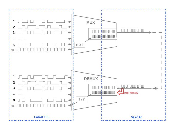
- The figure is also useful to point out (in red) the point where the combined signal/clock is to be regenerated. The fundamental first operation is the Clock Recovery from the combined Clock and Data signal, an operation that is the subject of this book.
CDRs and PLLs
editThis book deals with CDR (Clock and Data Recovery) circuits, but just the PLLs (Phase Locked Loops) that they incorporate are the circuit blocks that are analyzed and studied.

These PLLs are the important part of a CDR (= used for the Clock Recovery, = the CR part of the CDR).
The DR (Data Recovery) part of the CDR is not studied in any depth, and only the PLLs that are fit for the Clock Recovery function are studied here.
PLLs used for other applications, like for instance position detection of mobile objects or identifications of non-modulated signals, are not considered.
In recent years, owing to the explosive growth of mobile phones, a lot of development has been made on PLLs inside frequency synthesizers (they are not CDRs). It may be said that nowadays a very large part of the PLLs implementations are in frequency synthesizers.
What is special in PLLs for CDRs is a direct consequence of the "blending" of information bits with their clock into a unique serial stream of pulses. Often a NRZ transmission of the information bits does the job perfectly. For other transmission channels a different "encoding" of bits and clock may optimize better the overall performances and increase the distance beyond which a regeneration is needed.
In all cases the "blended" serial stream, owing to the essential "impredictability" of the information bits, does not have a spectrum with neat lines at fixed frequencies but is spread out with large lobes; its level transitions do not occur at each of the possible instants but randomly on just part of them. The concept of "transition density" is used in this book to simplify the mathematics. Moreover, these transitions, when they occur, jitter with respect to their ideal positions because of channel distortion and noise.
On the contrary, the signal that a frequency synthesizer locks into, is a regular periodic waveform, with a spectrum close to a strong line with noise sidebands. Its level transitions occur with a 100% density.
Clock additional fare
editThe clock that travels together with the data
editThe clock signal that releases the data bits one by one for a serial transmission must travel with them and be recovered first upon arrival, so that the regeneration of the received data bits can follow.
To efficiently use ( a good percentage of ) the channel capacity, a practical serial link needs a clock that can correctly identify each data pulse at the arrival point. [2]
When data are transmitted in the simplest way (NRZ) each symbol is a pulse (0 or 1) lasting exactly one period of the associated clock. The associated clock is visible in ( and recoverable from ) the “transitions” (level changes from 1 to 0 or vice versa) between two subsequent symbols. Unfortunately a transition is not always present between two symbols. If transitions do not occur often enough (transition density, run-length,..), then it is not possible to recover the clock associated with the received data.
The train analogy
edit- To clarify the concept, a simple analogy can be used, of a train transportation where some additional passengers are added to each given group of normal (data bit) passengers.
- These additional passengers are going to assist the others upon arrival, but decrease the number of seats available to the original passengers, that pay for everybody (the group of paying passengers that use a reduced number of seats represents the payload in this analogy).
- The recovered clock is necessary to regenerate the data passengers when they get out of the train. This (recovered) clock is necessary to fully regenerate every data bit passenger. No other clock can accomplish that.
- Amongst all the added passengers that accomplish their task at the arrival (receiver), some assist in the clock recovery, but others may be present to correct the most deteriorated passengers that might have arrived in a terrible state and have been regenerated wrongly (Bit error correction), and some others might be present for a combination of these types of tasks (framing, etc.).[3]
The fundamental theory
editThe fundamental theory based on the Shannon-Hartley theorem, does not address explicitly the clock recovery topic, because its synthetic formula applies exactly only to
- linear systems and to
- the most generic and casual type of noise (gaussian):

- The theorem does not consider also that the total time available to achieve a complete regeneration of the received bits is in practice very short.[4]
Still the hypotheses for validity of this "channel capacity theorem" indicate that:
- the continuous transmission yields results closer to the theoretical limit than burst transmission and that
- recourse to complicated encoding schemes is needed for real systems to improve towards the theoretical limit [5].
The meaning of this fundamental formula extends much beyond its stated hypotheses.
Its popularity in fact comes from the understanding it offers in reality, where bandwidth and noise are not known with mathematical precision and where many relations between quantities deviate significantly from linearity.
It provides good approximations when applied to non-linear phenomena, for instance to the bit error rate that originates from the phase noise affecting the transitions of the received signal (i.e. to the clock jitter).
- The phase noise that deteriorates the clock ( the clock is essentially a square wave and is affected by a noise that is nothing but the jitter) increases the bit error rate BER (i.e. reduces the theoretical channel capacity C) very much like a reduction of the signal to noise ratio ( S/N ) does in the formula of Shannon-Hartley.
- Strictly speaking, the formula yields exact results only if the noise is gaussian. But the gaussian noise is the most random possible noise and the recovered clock phase noise comes from the cumulation of many different disturbances. It can be understood that both noises produce a higher BER (i.e. both reduce the channel capacity C) even if by (slightly) different amounts.
The actual additional fare
editHow large is the cost (in terms of bit rate, or of channel bandwidth, or of channel capacity) that is paid in actuality to have the clock travel together with the associated data?
The Shannon-Hartley theorem does not tell how to conceive a system that meet the given requirement of practical cases, and the implementation task is passed to design engineers without concise formulas to use.
All the transmission equipment are designed to be compatible with the longest line length they may happen to be used with.
In all of them, the design of the clock recovery circuits are made so that the jitter of the recovered clock is kept small enough not to generate but a possible minor increase of the bit error rate, even when connected to the longest w:Communication channel they are specified for.
In other words, the clock jitter makes a negligible contribution to the total equivalent S/N, but this is achieved at the cost of reducing the number of passenger seats, i.e. with a reduction of the net bit rate, that is in turn equivalent to a reduction of the available bandwidth B.
In most real cases the channel capacity reduction traded off in return for an error free clock recovery ranges from maximum larger than 10% (burst transmissions) down to a few percent (continuous transmission). [6]
What this book is all about (i.e. application-structure correspondence)
editThis book intends to provide a good theoretical base for the understanding, the study and the engineering of PLL systems meant for CDR applications.
The PLL of a CDR is a unity feedback system because the output (the recovered clock) should be as close as possible to the input (the clock embedded in the incoming pulse stream), apart from the rejection of high frequency components of the latter.
CDRs that are made up entirely of circuit blocks that behave linearly are well described by the linear mathematical models, i.e. by linear differential equations with time as independent variable and by their Laplace or Fourier transforms.
Any PLL of a CDR can be described by one out of three "control loop structures" (= architectures, in the sense of block diagrams).
They can be identified just by the two numbers of their order and their type. The figure here below identifies the three architectures from their linear models.

The structures implemented in practice with all linear blocks are:
- Loops of 1st order and of type 1, for applications of "phase aligners" and of "end points".
- Loops of 2nd order and of type 1, for applications of "regenerators"
CDRs with one or more hard non-linearities can not be sufficiently described by linear mathematical models. ( Additional simulations recomputed for each different signal level are needed).
- The widespread (and often inevitable) use of essentially non-linear phase comparators (bang-bang) leads to the use of the more tolerant and robust architectures. (The gain of the bang-bang phase detector is not fixed, but varies with the phase difference at its inputs).
Such structures can still be identified by the numbers of order and type of the corresponding linear loops,

and are in practice:
- Loops of 1st order and of type 1 (exactly as in 1.1.), for applications of "phase aligners" and of "end points".
- Loops of 2nd order and of type 2 (if a linear phase comparator is used this structure is non-preferred) for applications of "regenerators" and of "end points". A detailed analysis of a linear (2.2) architecture (with all linear blocks) is still very important for the comprehension of its practical applications with a bang-bang phase detector.

In the book, for all the listed cases (1.1., 1.2. and 2.2.):
- the linear model (functions of the complex variable or of , and of the real variable ) is provided, so that the operation in "small signal" conditions can be studied (jitter tolerance, jitter transfer, noise transfer, unit step response, etc.)
- of each PLL block and
- of the overall system
- Important points, where the linear model applicability is exceeded, are investigated, using results obtained trough numerical simulation.


- Several versions of simulation programs have been developed and can be provided on request [7] .
Notes
edit- ↑
Parallel: one transmission line for each bit in the word, with all bits of a word transferred at the same time
- Parallel is always Synchronous (i.e. there is one more transmission line for the clock that identifies each word)
- The bits of each word may - in theory! - be serialised either Least Significant Bit First, or Most Significant Bit First w:Bit numbering, but in actuality the bytes inside a word may be be serialised with one endianness and the bits inside a word with the other endianness. However, the byte and bit endiannesses of the standard used in any particular implementation do not matter for the CDR engineering.
- Serial is practically always Synchronous:
- a clock identifies each bit,
- the serial bit stream and the clock are mixed together for transmission
- The conbined transmitted signal may or may not include enough clock information, depending on whether it meets some transition density (or run-length) requirements
- ↑ file, in the sense of file, Etymology 1, 4.: "An aggregation of data on a storage device, identified by a name."
- ↑ Unless additional (and complex) tricks are used, the parallel transmission is impossible beyond a certain distance. To put the shifted streams of bits back in sync, it would be necessary to insert redundant bits inside each bit stream at the transmit stage, so that a frame sync can be detected at the receive end. Then buffer memories at the end of each path would be needed to put back in sync all the bits of the parallel paths. Interfaces with this structure have been proposed, and are in use in some systems.
- ↑
A serialised transmission, with clock and data encoded together on a single link, is necessary when different links travelled by parallel signals (clock included) differ by 50% or more of a bit period at their bit rate. It is preferred when +/- 25% may be exceeded.
It should be emphasised that the serial transmission needs a multiplexing of the n bits of each word before transmission, and demultiplexing at the end, to present in parallel the bits of every word. The serial transmission takes place at a bit rate n times higher than the corresponding parallel transmission.
The length of a serial link does not need to match with accuracy the length of another link. Serial always preferred for all types of transmission lines when the distance is longer than a few meters. Often serial transmission is used even for shorter distances.
The serial transmission is only limited by the total length its transmission technique can reach. Using optical fiber this means from hundreds of meters to more than a hundred kilometres.
For example: at 1 Gbps the wavelength to refer to is:- c/(1 GHz) = 3 * 108 m/s / 109 sec-1 = 30 cm.
As a result, serial encoded transmission (at n-times 1 Gbps, e.g. 8 Gbps if the parallel links are 8) becomes preferred when distance differences amongst the parallel paths (used at 1 Gbps) are 5 cm or more.
If copper of fiber cables are considered (equipment backplanes or inter-equipment), the choice of serial becomes more advantageous, because of the larger cost of the parallel cables and connectors.
References
edit- ↑ FED-STD-1037C.PDF, page 414 of 498
- Transmission line: The material medium or structure that forms all or part of a path from one place to another for directing the transmission of energy, such as electric currents, magnetic fields, acoustic waves, or electromagnetic waves.
- Note: Examples of transmission lines include wires, optical fibers, coaxial cables, rectangular closed waveguides, and dielectric slabs.
- Downloaded from http://www.everyspec.com Wed Sep 20, 2017
- ↑
- Ideally, but only ideally, the clock may have followed a separate, parallel path.
- The shortcomings of a separate clock path have been described already in this Introduction page, from a slightly different point of view, when evaluating the distance limitation for multiple data links in parallel (limitation that happens to be very similar whenever a parallel clock path is considered, like in this paragraph).
- ↑ In actual data networks there are clocks that follow dedicated parallel paths ( something analog to special trains, comfortable and exclusively for clock passengers ).
They reach their destinations in very good conditions and can then travel on departing trains with normal passengers that have also reached the same station.
These passengers groups can take advantage of a new clock, cleaner than the clock that has travelled with them, but only after having been regenerated by the very clock that travelled with them and shared in the same discomforts (that has suffered their same distortions). - ↑ Such time is just one amongst many contributors to the total latency experienced by the final users and must therefore be kept to a minimum.
For many applications, both for real time transmission as well as not, the total latency between network nodes (where several clock recovery, de-framing, level 2 and 3 packet routing take place) is preferably kept below twenty-some milliseconds. (For instance, the overall latency of an audio call as experienced by the final users must be kept below a total of 200 ms). - ↑ MIT News article on Shannon Limit
- ↑ For a satisfactory clock recovery, different techniques are used in different cases. Very often more than one are present together in the same application, but almost all of them consist in taking a limited amount of line pulses and assigning them to clock recovery (and to other) purposes. The useful bit rate is correspondingly reduced and so is the Channel Capacity in the Shannon-Hartley sense.
How large is the cost (in terms of bit rate, or of channel bandwidth, or of channel capacity) that is paid in actuality to have the clock travel together with the associated data?
Owing to the many different solutions present in digital networks, and to the additional purposes that each solution may serve besides clock recovery, the answer can only be approximated by a range of possible values.
It must also be considered that a payload of bits is loaded with additional overhead bits every time it goes down a step in the staircase of the OSIRM levels to reach the bottom and become a train of pulses actually transmitted through the physical medium.
Each additional overhead helps create a train of pulses that make the clock recovery a bit easier, even though it is the overhead added by the lowest layer that is primarily meant to directly assure the clock recovery.
In burst transmissions the seats (bit intervals) at the beginning of each burst are denied to the paying passengers. The sequence of pulses transmitted first is chosen to generate a large number of transitions, to allow a very fast clock recovery. The phase lock of the clock is reached within the shortest possible time and all the data bits that follow can be correctly regenerated.
In continuous transmissions there is no such consideration, because a longer time can be allocated to reach phase lock (the event of beginning of transmission is a rare occurrence and its duration has a negligible impact on the overall efficiency).
In the extreme case of very short links with over-abundant bandwidth, differential Manchester is sometimes used instead of NRZ.
Differential Manchester should be seen as an extreme case. The channel bandwidth required is twice as large with no increase of the channel capacity, in return for excellent clock recovery and other benefits (extremely low signal power at frequencies close to 0 and insensitivity to polarity inversion, constant signal power,..). The total additional fare for the added passengers is 50%, the majority of which may be ascribed to the clock.
8b/10 encoding takes two additional seats every 8 mainly to make sure that the clock can be easily recovered in continuous transmissions. (The analogy with the addition of 2 non-paying passengers gets a bit confused in this case, because the overall group of 10 bits is not simply made adding two new ones and keeping the eight original bits: there is some scrambling involved. The original group of 8 passengers is not identifiable along the trip, but is recreated at the arrival). The clock added fare accounts for the majority of the capacity reduction of (10-8)/10 = 20%.
The 64B/66B transmission code is a more recent and less overhead version of 8b/10b. It is used in the Fast Ethernet, Gigabit Ethernet, and 10 Gigabit Ethernet standards. The channel capacity reduction is (66-64)/66 = 3 %, but the clock receives only an assurance of 1 more transition every 66 bits. The clock additional fare can be computed as 1.5 %. To compensate for some advantages of 8b/10b, it is used always with scrambling that alleviates statistically its lower performances in DC balance, run length, and transition density.
In most real cases the channel capacity reduction traded off in return for an error free clock recovery ranges from maximum larger than 10% (burst transmissions) down to a few percent (continuous transmission). - ↑ Requests can be mailed to: plz.pllsmltor.file@gmail.com . The simulation programs accept as inputs the loop parameters and the input signal characteristics and provide as output a representation of the "large signal" behavior in those conditions, e.g. of the loop acquisition waveform