Routing protocols and architectures/Open Shortest Path First
Open Shortest Path First (OSPF) is an intra-domain routing protocol based on the Link State (LS) algorithm. The first two versions are used with IPv4, while version 3 is thought for IPv6.
The main advantage of OSPF with respect to other intra-domain routing protocols is scalability (up to some hundreds of routers):
- LS algorithm: the knowledge of network topology allows a greater stability with respect to protocols based on the Distance Vector algorithm;
- hierarchical routing: OSPF suggests not to have more than 200 routers in a single area:
- routing information about other areas can be summarized;
- route changes in an area do not perturb other areas.
Areas
edit
OSPF defines its own terminology, which is not always aligned to the one of other protocols:
- Autonomous System (AS)
- a domain under the control of a single entity from the administrative point of view (e.g. GARR)
- OSPF Autonomous System
- a domain under the control of a single entity from the technical point of view (i.e. device configuration), and handled by a single OSPF protocol instance
- Autonomous System boundary router (ASBR)
- a border router put between the OSPF AS (typically area 0) and an external routing domain (EGP, or IGP if the OSPF AS lives within the AS itself together with other routing domains with even different IGP protocols)
- edge area
- one of the hierarchical sub-domains in which an OSPF AS is split, made up of a physically contiguous network: each internal router can communicate with any other router within the same area without having to exit the area itself
- area 0
- the backbone area, not necessarily physically contiguous (
 #Partitioned areas), which all traffic between one edge area and another or between one edge area and the outside of the OSPF AS must go across:
- no bottleneck: links should not be undersized
- robust: it should not become a partitioned area
- area border router (ABR)
- a border router put between area 0 and an edge area

Every router perfectly knows the topology of the area it belongs to, but the precise topology of other areas is unknown: the router may know the list of destinations reachable outside its area, which can be summarized or replaced by a default route.
The database of an internal router contains three types of records:
- Link States: they are generated by other internal routers within the area and contain internal routes within the area, including topology information, which are never summarized.
An ABR knows Link States from both the areas which it connects: it has multiple databases, one for each area, which of course originate a single routing table; - Summary/External Records: they include external routers outside the area, excluding topology information (just network address + netmask), which can be summarized:
- Summary Records: they are generated by the ABR and contain the external routes inside other areas within the same OSPF AS (including area 0);
- External Records: they are generated by the ASBR and contain the external routes outside the OSPF AS.
Routers in area 0 are usually configured in order to aggregate network addresses, so as to propagate network summaries from one area to another one. However aggregation must be specified manually by the operator, in order not to have troubles with network summarization.
Stub areas
editA normal edge area, besides knowing details about topology of all internal routes within the area itself, imports all external routes from area 0 without any further aggregation.
An area is stub when some external routes are replaced by a single default route to reduce the routing information imported from outside:
- stub area: it keeps Summary Records, but removes External Records;
- totally stubby area: it removes both Summary Records and External Records, leaving only Link States and the single default route toward the exit;
- not-so-stubby area: it is similar to the stub area, but it can inject into other areas the external routes outside the OSPF AS (without importing them into the area).
Stub areas are enabled upon an explicit configuration by the network manager:
- stub area: area xx stub
- totally stubby area: area xx stub no summary
- not-so-stubby area: area xx nssa
Although OSPF does not prevent from having a stub area with more than one ABR, it makes more sense to configure a stub area when it is connected to area 0 through only one ABR: external routes do not need to be propagated because there is only one path which connects the area to the rest of the network, while external routes are useful only if more than one egress router exists.
Virtual Link
editThe Virtual Link is a sort of 'tunnel' between two routers, of which at least one belonging to area 0, which logically belongs to area 0, but physically is made up of a sequence of links inside an edge area. The purpose is to make OSPF believe that those two routers are connected by a fictitious link in area 0.
Enabling the Virtual Link only requires the area to be crossed (only one) and Router IDs of the two involved routers, not the IP addresses of their interfaces: OSPF will automatically derive the correct IP addresses. OSPF routing messages are encapsulated into IP unicast packets crossing the link → to have a bidirectional tunnel, the Virtual Link needs to be configured on both the routers at the ends.
Partitioned areas
edit-
 Partitioning of an edge area.
 -
 Partitioning of area 0.


The problem of partitioned areas is handled in OSPF differently depending on the type of area:
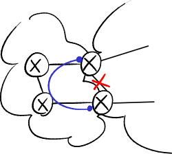
- edge area: the ABR does not summarize the information about all the networks present in the edge area, but only announces the networks which it is able to reach → packets toward the partition will be sent only to ABRs for which an internal path exists to arrive at the destination;
- area 0: OSPF is not able to automatically solve problems of partitioned areas in the backbone (the closest ABR is always chosen as the exit point), but in some cases the operator can manually enable between two ABRs a Virtual Link which physically crosses an edge area: when a packet arrives at an ABR, it goes back to the area going to the ABR at the other end of the tunnel and then at last enters area 0 → area 0 must always be logically, but not necessarily physically, contiguous.
Extending the backbone area
edit
A link between two routers belonging to different edge areas normally can not be used: traffic from one area to another one in fact must always cross area 0.
Thanks to the Virtual Link it is possible to bring into the backbone a router in an edge area which is directly connected to a single backbone router: that internal router becomes an ABR to access area 0, and then all links connected to it can be used for traffic.
Metrics and costs
editOSPF supports more than one metric simultaneously on a single link: the best path can be, depending on packets, for example
- the shortest path;
- the path with the best bandwidth capacity;
- the path with the lowest delay.
OSPF allows to define metrics depending on the 'Type of Service' (ToS) field in the IP packet → in theory, 64 types of service and then 64 different routing trees are possible, but in practice this feature is almost unused because the processing load required by the LS algorithm on each router would be duplicated for every ToS.
OSPF adopts equal-cost multipath routing. Differently from IGRP, OSPF does not define an unambiguous way to compute the cost of a link: the cost is assigned by the manufacturer of the network device → each manufacturer has its own default values, creating possible inconsistencies in multi-vendor networks → it is better to customize the cost values on the most important links (on both ends).
Router ID
editEach OSPF router is uniquely identified by a Router ID, which is used as the 'name' for routers in OSPF packets (e.g. as the source in the OSPF header).
OSPF does not specify how the Router ID should be determined, but just specifies that it must be a 32-bit-long unique identifier. On Cisco devices, Router IDs can be obtained in two ways:
- manually: the network administrator explicitly configures the value of the Router ID (in IPv4 typically this is not done, while in IPv6 this is mandatory: B6. Instradamento IPv6#OSPFv3;
- automatically: an algorithm gets the Router ID from the IPv4 addresses of the router:
- if at least a loopback interface exists, the Router ID is equal to the biggest address among the ones of the loopback interfaces: loopback interfaces do not depend on the state of the physical interfaces and are thus more stable;
- if no loopback interfaces exist, the Router ID is equal to the biggest address among the ones of the OSPF network interfaces.
LSAs
editLink State Advertisement (LSA) is the data structure, contained in Link State Update packets, which includes OSPF routing information:
- Router LSA: it describes an adjacency via a point-to-point link;
- Network LSA: it lists the routers attached to a transit network, and it is generated by the designated router of the transit network;
- Network Summary LSA: it contains the external routes inside other areas within the same OSPF AS (Summary Records), and it is generated by an ABR;
- ASBR Summary LSA: it notifies the location of the ASBR if it is not in area 0 but in an edge area;
- AS External LSA: it contains the external routes outside the OSPF AS (External Records), and it is generated by an ASBR.
Router LSA
edit- Adjacencies seen from router R1.
-
 Single router.
 -
 Router link.
 -
 Network link.


OSPF defines two types of link:
- router link (default): if there is a point-to-point link between two routers (e.g. serial interface), each of routers sees it as logically split into two point-to-point links:
- a point-to-point connection to the adjacent router, identified by its own Router ID;
- a point-to-point connection to the adjacent IP network, called stub network[1], that is the one which the network interface of the router belongs to.
If a router interface is enabled but is not attached to any other router, there is only the connection to the stub network (single router figure);
- network link (network link figure): if there is a broadcast network (e.g. Ethernet), called transit network, each of the two[2] or more routers attached to it sees it logically as a point-to-point connection to the adjacent transit network.
LSA Routers can describe several types of adjacencies via point-to-point links:
- adjacency to a router: it is generated by each of the two routers adjacent one to each other;
- adjacency to a transit network: it is generated by each of the routers adjacent to the transit network (including the designated router);
- adjacency to a stub network: it is generated by the router whose interface is adjacent to the stub network;
- adjacency to a Virtual Link: it is generated by each of the routers at the ends of the Virtual Link.
OSPF packets
editAll OSPF packets are directly encapsulated into IP (Protocol Type = 89), without any help from an intermediate transport protocol.
An OSPF header, the same for all packets, specifies the type of transported OSPF packet:
- type 1: Hello
- type 2: Database Description
- type 3: Link State Request
- type 4: Link State Update
- type 5: Link State Acknowledgement
Hello protocol
editThe hello protocol performs the fault detection without relying on the physical layer.
Hello packets are sent every HelloInterval (default = 10 s), and the adjacency is considered as disappeared and is no longer announced:
- as soon as the fault is detected at the physical layer;
- after a certain amount of lost Hello packets (default RouterDeadInterval = 40 s, equivalent to 4 Hello packets), if the fault can not be detected at the physical layer.
The LSA however remains in the OSPF database, and if not renewed it will expire after a period of time equal to MaxAge (default = 1 hour).
The Router ID is computed at the start of the OSPF process, and it is not modified even if the IP addresses on the router are modified → the router may appear with a different Router ID on reboot of the OSPF process (e.g. following a fault or a power outage) → in the topology computed by the LS algorithm a no longer existing node remains, until its LSA will expire.
Exchange protocol
editThe exchange protocol is used to perform the adjacency bring-up, that is to synchronize the database of two routers when they become adjacent.
The adjacency bring-up is performed only when needed, that is when a router has some not updated information in its database. Checking the need for a database update is performed:
- after a change in the network (e.g. at boot time or when a new link becomes active);
- whenever the LSA Refresh timer expires (default = 30 minutes), to refresh the ages of still valid LSAs before they expire.
During the adjacency bring-up, only old or missing LSAs are exchanged:
- Database Description: the master router sends the list of sequence numbers of all the LSAs in its database;
- Link State Request: the slave router sends the list of sequence numbers related to old or missing LSAs in its database;
- Link State Update: the master router sends the requested LSAs, and the Link State Update packet is propagated in selective flooding;
- Link State Acknowledgement: the slave router confirms it has received the Link State Update.