Practical Electronics/IC/4072
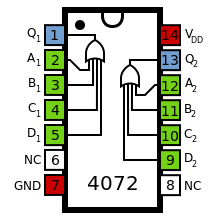
The 4072 is a member of the 4000 Series CMOS range, and contains two independent OR gates, each with four inputs. The pinout diagram, given on the right, is the standard four-input CMOS logic gate IC layout:
| 4072 | |
|---|---|
| Logic Type | Combinatorial |
| Function Family | Logic |
| Description | Dual 4-Input OR Gate |
| Pins | 14 |
| Pinout | |
 | |
| Functional Diagram | |
 | |
- Pin 7 is the ground supply (GND)
- Pin 14 is the positive supply (VDD)
- Pins 2-5 and 9-12 are gate inputs for the two gates
- Pin 1 and 13 are gate outputs
- Pin 6 and 8 are not connected
The truth table for one of the two gates is shown below. For more information about the OR gate in general, see this module.
Truth Table for a Single Gate
| A | B | C | D | Q | |
|---|---|---|---|---|---|
| 0 | 0 | 0 | 0 | 0 | |
| 0 | 0 | 0 | 1 | 1 | |
| 0 | 0 | 1 | 0 | 1 | |
| 0 | 0 | 1 | 1 | 1 | |
| 0 | 1 | 0 | 0 | 1 | |
| 0 | 1 | 0 | 1 | 1 | |
| 0 | 1 | 1 | 0 | 1 | |
| 0 | 1 | 1 | 1 | 1 | |
| 1 | 0 | 0 | 0 | 1 | |
| 1 | 0 | 0 | 1 | 1 | |
| 1 | 0 | 1 | 0 | 1 | |
| 1 | 0 | 1 | 1 | 1 | |
| 1 | 1 | 0 | 0 | 1 | |
| 1 | 1 | 0 | 1 | 1 | |
| 1 | 1 | 1 | 0 | 1 | |
| 1 | 1 | 1 | 1 | 1 |
This chip is widely available, and usually comes in a DIL-14 or SOIC-14 package.