Plastics Molding & Manufacturing/Mould design
The design of moulds is a complex activity that requires to take care of many aspects, from the shape of the manufact, to the smallest details of cooling system.
Introduction
editGenerally, moulds for injection moulding are made for mass production of quite simple parts and components that can be later assembled to produce complex products. The reason why the parts must be quite simple is that they must be extracted from the mould in which it is made by solidification of the plastified flow injected in.
The cost of moulds is generally between some tens of thousand Euros to some hundreds of thousands Euros.
The time for projecting and manifacturing a mould is between few weeks and several months.
Moulds classification
editThere are many kind of moulds, that can be classified by many different criteria: production volumes, demolding system and direction, runner system, etc.
By production volumes
editMoulds require high cost and high time usage for their construction, for this reason they are generally used for big productions (at least many hundreds or thousands manufacts). Generally normal moulds made in steel are made for annual production of numbers of parts from 10,000 to many million parts.
Moulds for small production or pilot tools (for testing feasibility of the moulding process and study of the behaviour) are made in easily workable and cheaper alloys (as aluminium).
By demolding system
editEvery part produced by a mould must be removed from it. For this reason the part can be removed by natural fall, by ejection and fall, by automatized extraction (by external robot), by manual removal, etc.
Furthermore, injection moulding machines can be horizontal or vertical, so the mould can be designed for the corresponding clamping system.
By runner system
editMoulds can be classified as cold runner, hot runner or hybrid.
By number of ejection plates
editThe basic mould mechanism counts only one ejection plate that moves the ejectors in order to extract the part. Nevertheless, it is really common to use more than one moving plate in order to extract complex parts with undercuts.
Materials for moulds
editMaterial Description
ABS Common thermoplastic with good impact resistance and toughness. Polypropylene Thermoplastic polymer used for a wide number of applications. Polyoxymethylene Dimensionally stable thermoplastic with high stiffness and low friction. Polycarbonate Thermoplastic material with good temperature resistance and impact strength. Polycarbonate / ABS Blend of PC and ABS that creates strong parts for a variety of applications. PVC PVC is a polymer with good insulation properties, high hardness, and good mechanical properties. Nylon Polymer material that is durable with high elongation and good abrasion resistance. Nylon 32% Glass Fiber Polymer with excellent mechanical stiffness and elevated temperature resistance. Acrylic (PMMA) Material with resistance to breakage often used for transparent applications. Styrene Light weight material popular for its high impact strength and toughness. Polyetherimide Thermoplastic with high heat resistance and excellent mechanical properties.
Manufact cavities
editThe cavities for moulding are realized in several ways, they must follow dedicated design rules, they can have several sizes and shapes.
General design rules
editThe design of parts to be moulded must fit the following needs:
- It must be possible to fill the part with plastic fluid, that is:
- The part must be a continuous solid (otherwise multi-injection point must be contemplated)
- Walls cannot be too thin
- Flow length cannot be too long
- The air present in the cavity before injection must have the possibility to be evacuated (see gas venting) or compacted in non-visible zones
- The fluid must cool down and solidify quickly, that is:
- The heat must be evaquated by a cooling system
- The part cannot have very deep and bulky zones, they must be emptied, leaving only structural ribs
- Plastic materials have a significative volumetric shrinkage during solidification (about 0.5 - 3.0 %), so the cavity dimensions on the mould must be scaled up in order to have the desired measure for the part once completely shrinked at usage temperature.
- The part must be demouldable, that is:
- The part must not have undercuts (or contemplate movements for each of these, otherwise the part must be separated and manufactured with several moulds or cavities)
- A draft angle must be present on all vertical walls; it must be directed to the division line of each half
Special rules
edit- Plastic materials, especially if not isotropic, can lead to an asymmetric shrinkage of the moulded part: for this reason it can be useful to design the mould with a pre-deformed shape such that the resulting shape corresponds to the desired one once the part is completely shrinked.
- Some superficial patterns or roughness create micro undercuts that cannot be demoulded and ejected correctly on vertical surfaces.
- Certain superficial finish can require a special material for the cavity (e.g. mirror polished surfaces)
- If the part must be handled by a robot after ejection, the part must contemplate features to enable the pick by vacuum sucker or tongs.
Realization techniques
editThe cavities are generally realized by subtractive manufacturing with machining tools. Nevertheless, many details and particulars can be obtained with other methods or technologies. Main technologies used are:
- Machining (milling, drilling, [[w:grinding|grinding], polishing)
- Electrical discharge machining (EDM)
- Additive manufacturing
- Electrochemical machining (ECM)
- Laser engraving
- Welding (only for repair or modification)
Mouldmaking makes large use of normalized elements, such as structural blocks, data-clocks, mechanical movements, etc.
The most typical flow of jobs for the realization of a mould:
- Mould project realization
- Purchase of metal blocks and normalized blocks
- Roughing of metal blocks
- Finishing of cavities
- Superficial finish of cavities
- Assembly
- Mould testing (dry and mounted on injection machine)
Runners systems
edit
The runner system consists in the channel system that links the injection nozzle of the injection moulding machine to the gates that inject the plastified flow into the core cavities.
Its parts are generally denominated as:
- sprue (first straight channel)
- primary runner and secondary runners (branches starting from the sprue and then by the primary runner, for multi-cavity moulds or multiple injection points)
- gates
Even though the sprue is present only in cold-runner systems, some common elements are present also in hot-runner systems or hybrid systems.
Sprue
edit
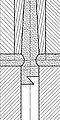
The sprue channel is originated by a sprue bushing that conveys in the channel the plastic flow coming from the nozzle of the press. The sealing of the channel with the nozzle is obtained by contact only, by the force applied from the machine to the cylinder. The following relations are generally respected in order to correctly seal the contact and guarantee easy demolding and no freezing of the zone before the completion of the complete part[1]:

- The spherical radius of the nozzle R must be minor or equal to the radius of the indentation of the sprue bushing r (generally it is 1 mm less).
- The diameter of the orifice of the nozzle dN must be minor or equal to the diameter of the orifice of the sprue bushing entrance dD (generally it is 1 mm less).
- The sprue must be tapered, generally recommended with an angle of 4°, or at least 1°.
- The diameter of the sprue bushing must be limited, in order to avoid stresses due to temperature gradients and force for sealing. This component is generally at an higher temperature rather than the mould half.
Commercial sprue bushings are also available.
In single-cavity moulds, the sprue is generally demolded together with the part that is held by the moving half, while in multi-cavity moulds a sprue puller is used to hold the sprue in the moving half. Sprue pullers are generally short conical indentations generally placed in correspondence with the end of the sprue, in the moving half, tapered as the sprue, acting as an undercut.[2]
-
 z-shaped sprue puller
 -
 Cilindrical sprue puller
 -
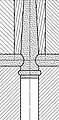 Grooved sprue puller


Sprue puller can act also as cold slug well: a cavity in which the hot plastified material can freeze in contact with the mould, without being transported in the cavity causing superficial defects on the part.
Runners
editThe runners convey the material from the sprue channel to the gate, they must:[3]
- freeze after the gate and the part is freezed, so their thickness should be major to the thickest wall section of the part (generally recommended D = smax + 1.5 mm)
- follow a short path: for short cycle-time, late freezing, low material waste and low pressure loss (generally recommended < 30 MPa)
- generally not be polished, for a good adhesion of the frozen skin in the runner rather than flowing in the part (except for some material where it is recommended to polish them, suche as PVC, polycarbonate and polyacetal)
-
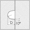 U-shaped or parabolic runner section, very common, usually indented in movable side of the mould for a good ejection
 -
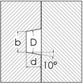 Trapezoidal runner section, producing more heat exchange and scrap due to higher perimeter and cross area, usually indented in movable side of the mould for a good ejection
 -
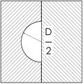 Semi-circular runner section, not particularly favorable for ejection due to low draft angle
 -
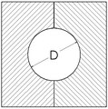 Round runner section, not particularly favorable for ejection due to low draft angle; more expensive ant time wasting for indentation needed on both sides of the mould


Cold-runner system
editCold-runner systems produce parts with sprue. Multi-cavity moulds need a sprue plus a primary runner and, if needed, a certain number of secondary runners (if more than two cavities are present). The same happens for parts that are projected with more than one injection point.
The runner are dimensioned for equally distributing material flow to all the cavities: having a good distribution of the material is a hard goal, due to high sensibility of the fluid dynamics to the imperfections of the surfaces, non-homogeneous plastic material properties and other indirect factors. In case that the mould produces parts with different shapes, then the runners need to distribute the material flow not equally but in proportion to the volume needed to fill each part with similar time, pressure, speed.
The sprue for termoplstics can generally be reused if regrinded, at the end of the lot or with a grinder next to the injection moulding machine. The reuse of the sprue, as every reuse of moulded plastic, can change and degrade the properties of the plastified flow and can cause defects in the injected part: for this reason, for high quality results, it can be accepted to regrind the sprue only if the percentage of reused material per each shot is limited (10-20% of the total mass).
This system can be used with both thermoset and thermoplastic materials.
Hot-runner system
editHot-runner system is a system that can increase efficiency in injection moulding and increase quality. Nevertheless, this system can be used only with thermoplastic materials, because the sprue cannot be ejected in solid state (it is melted again and used as raw material to produce the first parts).
If finely optimized, this system can be more efficient especially in reason of the absence material waste for sprues, lower cycle time and lower quantity of defected parts. On the other side, this system requires an higher investment for the mould and an increase of energy consumption for heating the hot-runner.
The system consists in a block of the mould containing a hot manifold that keeps material melted in the first zone of entrance of the material in the mould. This block is made of several plates joined together, containing manifolds that convey the plastified flow to the cavity and, if needed, distribute it to the several injection points by nozzles. Between the plates also electrical resistances and thermocouples are placed in order to heat the manifolds and control their temperature.
A controller is needed to control the temperature of the hot-runners and the current intensity in the electrical resistances. Generally more there are several circuits that can be controlled separately. This control makes easier the control of the process for multi-cavity or multi-injection point moulds. It is common to have a control of temperature for the zone of the manifolds and a control of temperature for each of the nozzles: this is really helpful to control the viscosity of the flow in each cavity of a multi-cavity mould, in order to balance it.
The system allow to not use a sprue, because it keeps it in melted status, without the need to demould it.
Nevertheless the plates containing the cavity need to be kept at a temperature that is lower than that of the hot-runner plates: this is achieved by isolation and cooling.
In synthesis:
- Advantages:
- absence of sprue to be demolded
- improved part quality
- improved process control (especially for multi-cavity or multi-injection moulds)
- Disadvantages:
- usage limited to thermoplastic materials only
- increased investment for hot-runner system and controller
- increase of energy consumption for heating the plastified material
- increase of difficulty in heat exchange isolation and cooling of the fixed part
Runners layout
editThe layout of the runners depends on several factors:
- equal distribution of flow rate and pressure over the gates (for a muti-cavity mould or a part with multiple injection point)
- simple manufacturing and designing of the mould
- easy de-mouldability (by classic ejection or robotized systems)
- gate design
- no of runners used.
A simple and generally recommended layout is to have 2n cavities and a path "H-like" path for runners, that easily allows to equally space the cavities and the flows. In this case, the channel sections must be simply reduced of a half for each bifurcation. This leads to moulds with 1, 2, 4, 8, 16, etc. cavities.
Nevertheless several reasons can favour a different layout, for example:
- reasons of cost and simplicity may suggest to have a linear layout when a common movement can be used for many cavities, avoiding the multiplication of moving parts, actuators and used space
- the need to fill the available space of the machine with a desired number of cavities (even though uneven number of cavities are always avoided for keeping the symmetry)
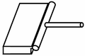
The runner system can include some sprue-puller or other geometries that are dedicated to enable or help the removal of the sprue by gravity or by robotized harm: an example are the flat disks used for robotized handling of the sprue and runners by suction cups.
Gates
editThe gate is the door of entrance of the material flow, it is generally:
- the thinnest channel where the material flows (excluding the case of the runner-gate)
- positioned in a non visible and non functional or critical point of the part
- sized in relation to:
- the thinnest wall of the part
- the properties of the material flow (viscosity, temperature, shrinkage, etc.)
The restriction of the flow section due to the gate causes a significante growth of the its temperature in the proximity of the gate, generally useful to fill thin walls of the part and postpone the freezing of the material in the zone of the gate.
Many possible configuration of gates are possible, due to ejection ease or quality of the part. Some possible gate designs:
- Tunnel gate
- Sprue gate
- Edge gate
- Radial gate
- Inverted sprue gate
- Circular gate
- Direct / Nozzle gate
- Shut off nozzle / Valve gate
-
 Sprue gate
 -
 Edge gate
 -
 Ring gate
 -
 Inverted sprue gate (pinpoint gate)
 -
 Direct hot nozzles


Some gate configurations helps the automatic removal of the sprue, such as tunnel gate, because the small junction point of the demoulded part is easy to separate mechanically at mould open or by handling robot. Sprue gates and edge gates are often separated manually or by a mechanical knife mounted on handling robot. Also the sprue-puller can be used to keep the sprue locked on the moving half longer than the cavities, in order to separate the two.
Ejection
editThe ejection of a part is a fundamental step of moulding, it is mainly executed by:
- mechanical ejectors movement: almost always present for ejecting parts out of the cavity
- air blow: not stressing the part locally, helpful for demoulding large parts
- robot handling: soft handling and parts not falling on the ground without possible deformation or superficial damage
- mould opening movement and gravity
The parts can also be ejected by combining the systems above. The sprue or different parts can be ejected differently: it is typical to remove the sprue by a sprue-picker robot, such that the sprue must not be selected among the parts later.
Heat exchange
edit- ↑ Georg Menges, Paul Mohren, "How to make injection molds", Munich, Hanser, 1991, p. 131, ISBN 3-446-16305-0
- ↑ Georg Menges, Paul Mohren, "How to make injection molds", Munich, Hanser, 1991, p. 133, ISBN 3-446-16305-0
- ↑ Georg Menges, Paul Mohren, "How to make injection molds", Munich, Hanser, 1991, p. 138, ISBN 3-446-16305-0