Introduction to Inorganic Chemistry/Ionic and Covalent Solids - Structures
Chapter 8: Ionic and Covalent Solids - Structures
edit
As we noted in our discussion of metal and alloy structures in Chapter 6, there is an intimate connection between the structures and the physical properties of materials. As we "graduate" from simple metal structures based on sphere packings to more complex structures, we find that this is still true. In this chapter we will try to systematize the structures of inorganic solids - metal oxides, halides, sulfides, and related compounds - and develop some rules for which structures to expect based on electronegativity differences, hard-soft acid-base rules, and other periodic trends. We will see that many of these structures are related to the sphere packings that we learned about in Chapter 6.
Learning goals for Chapter 8:
- Describe many crystal structures in terms of close-packed frameworks with systematic filling of octahedral and tetrahedral holes.
- Represent crystal structures by drawing them in sections.
- Rationalize, using chemical principles, why certain crystal structures are stable for certain compounds but not for others, as well as why certain structural and bonding motifs are preferred for certain compounds relative to others.
- Predict which crystal structures are most favorable for a given composition based on ionicity and periodic trends.
- Explain structure-dependent properties such as ferroelectricity and magnetic ordering based on crystal structures.
- Understand intercalation reactions in layered and open framework solids.
- Predict the preferred formation of normal or inverse spinels using arguments from transition metal chemistry (e.g. crystal field stabilization energies).
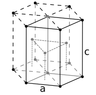
Inorganic solids often have simple crystal structures, and some of these structures are adopted by large families of ionic or covalent compounds. Examples of the most common structures include NaCl, CsCl, NiAs, zincblende, wurtzite, fluorite, perovskite, rutile, and spinel. We will develop these structures systematically from the close packed and non-close packed lattices shown below. Some layered structures, such as CdCl2 and CdI2, can be thought of as relatives of simple ionic lattices with some atoms "missing."
-
 Face-centered cubic (fcc) or cubic close-packed (ccp)
 -
 Hexagonal close-packed (hcp)
 -
 Body-centered cubic
 -
 Simple cubic


8.1 Close-packing and interstitial sites
edit
Many common inorganic crystals have structures that are related to cubic close packed (face-centered cubic) or hexagonal close packed sphere packings. These packing lattices contain two types of sites or "holes" that the interstitial atoms fill, and the coordination geometry of these sites is either tetrahedral or octahedral. An interstitial atom filling a tetrahedral hole is coordinated to four packing atoms, and an atom filling an octahedral hole is coordinated to six packing atoms. In both the hexagonal close packed and cubic close packed lattices, there is one octahedral hole and two tetrahedral holes per packing atom.
Question: Would anions or cations be better as packing atoms?
We might expect that anions, which are often larger than cations, would be better suited to the positions of packing atoms. While this is often true, there are many examples of structures in which cations are the packing atoms, and others in which the distinction is arbitrary. The NaCl structure is a good example of the latter.


In the NaCl structure, shown on the right, the green spheres are the Cl- ions and the gray spheres are the Na+ ions. The octahedral holes in a face-centered cubic lattice can be found at fractional coordinates (1/2 1/2 1/2), (1/2 0 0), (0 1/2 0), and (0 0 1/2). There are four of these holes per cell, and they are filled by the chloride ions. The packing atoms (Na+) have coordinates (0 0 0), (0 1/2 1/2), (1/2 1/2 0), and (1/2 0 1/2). Note that each of the Na+ positions is related to a Cl- position by a translation of (1/2 0 0). Another way of stating this is that the structure consists of two interpenetrating fcc lattices, which are related to each other by a translation of half the unit cell along any of the three Cartesian axes. We could have equivalently placed the Cl ions at the fcc lattice points and the Na ions in the octahedral holes by simply translating the origin of the unit cell by (1/2 0 0). Thus the distinction between packing and interstitial atoms in this case is arbitrary.
NaCl is interesting in that it is a three-dimensional checkerboard, and thus there are no NaCl "molecules" that exist in the structure. When this structure was originally solved (in 1913 by using X-ray diffraction) by W. L. Bragg, his interpretation met resistance by chemists who thought that precise integer stoichiometries were a consequence of the valency of atoms in molecules. The German chemist P. Pfeiffer noted in 1915 that ‘the ordinary notion of valency didn’t seem to apply’, and fourteen years later, the influential chemist H. E. Armstrong still found Bragg’s proposed structure of sodium chloride ‘more than repugnant to the common sense, not chemical cricket’! Nevertheless, Bragg and his father, W. H. Bragg, persevered and used the then-new technique of X-ray diffraction to determine the structures of a number of other compounds, including diamond, zincblende, calcium fluoride, and other alkali halides. These experiments gave chemists their first real look at the atomic structure of solids, and laid the groundwork for X-ray diffraction experiments that later elucidated the structures of DNA, proteins, and many other compounds. For their work on X-ray diffraction the Braggs received the Nobel prize in Physics in 1915.
Since each type of atom in the NaCl structure forms a face-centered cubic lattice, there are four Na and four Cl atoms per NaCl unit cell. It is because of this ratio that NaCl has a 1:1 stoichiometry. The shaded green and gray bipyramidal structures in the NaCl lattice show that the Na+ ions are coordinated to six Cl- ions, and vice versa. The NaCl structure can be alternatively drawn as a stacking of close-packed layer planes, AcBaCbAcBa... along the body diagonal of the unit cell. Here the uppercase letters represent the packing atoms, and the lower case letters are the interstitial atoms. This layered packing is illustrated below:
NaCl structure

- ------------ A
- - - -c- - - -
- ------------ B
- - - -a- - - -
- ------------ C
- - - -b- - - -
- ------------ A
- - - -c- - - -
- ------------ B
- - - -a- - - -
- ------------ C
- - - -b- - - -
- ------------ A
Note that both the packing atoms and interstitials are stacked in the sequence A-B-C-A-B-C..., in keeping with the fact that each forms a cubic close-packed lattice.

The NaCl structure is fairly common among ionic compounds:
- Alkali Halides (except CsCl, CsBr, and CsI)
- Transition Metal Monoxides (TiO, VO,..., NiO)
- Alkali Earth Oxides and Sulfides (MgO, CaO, BaS... except BeO and MgTe)
- Carbides and Nitrides (TiC, TiN, ZrC, NbC) -these are very stable refractory, interstitial alloys (metallic)
A number of other inorganic crystal structures are formed (at least conceptually) by filling octahedral and/or tetrahedral holes in close-packed lattices. The figure at the right shows some of the most common structures (fluorite, halite, zincblende) as well as a rather rare one (Li3Bi) that derive from the fcc lattice. From the hcp lattice, we can make the NiAs and wurzite structures, which are the hexagonal relatives of NaCl and zincblende, respectively.

An alternative and very convenient way to represent inorganic crystal structures (especially complex structures such as Li3Bi) is to draw the unit cell in slices along one of the unit cell axes. This kind of representation is shown at the left for the fcc lattice and the NaCl structure. Since all atoms in these structures have z-coordinates of either 0 or 1/2, only those sections need to be drawn in order to describe the contents of the unit cell. It is a useful exercise to draw some of the fcc compound structures (above right) in sections.
8.2 Structures related to NaCl and NiAs
edit
There are a number of compounds that have structures similar to that of NaCl, but have a lower symmetry (usually imposed by the geometry of the anion) than NaCl itself. These compounds include:
- FeS2 (pyrite, "fools gold"): S22- (disulfide) and Fe2+
- CaC2 (a salt-like carbide): Ca2+ and linear C22- anions
- CaCO3 (calcite, limestone, marble): Ca2+ and triangular CO32-.

The calcite (CaCO3) crystal structure is shown at the right. Triangular CO32- ions fill octahedral holes between the Ca2+ ions (black spheres) in a distorted NaCl lattice. As in NaCl, each ion is coordinated by six of the other kind. From this image we can see why the CaCO3 structure has a lower symmetry than that of NaCl. The fourfold rotation symmetry of the NaCl unit cell is lost when the spherical Cl- ions are replaced by triangular CO32- ions. Because of this symmetry lowering, transparent crystals of calcite are birefringent, as illustrated at the left.
NiAs structure. The NaCl structure can be described a face-centered cubic lattice with all of the octahedral holes filled. What if we start with a hexagonal-close packed lattice rather than a face-centered cubic lattice?

This is the structure adopted by NiAs and many other transition metal sulfides, phosphides, and arsenides. The cations are shown in gray while the anions are light blue in the figure at the right. The cations are in octahedral coordination, so each cation is coordinated to six anions. The anions are also coordinated to six cations, but they occupy trigonal prismatic sites. In terms of layer stacking, the NiAs structure is AcBcAcBc..., where the A and B sites (the hcp lattice) are occupied by the As atoms, and the c sites, which are eclipsed along the layer stacking axis, are occupied by Ni. Unlike the NaCl structure, where the anion and cation sites are interchangeable, NiAs has unique anion and cation sites. The layer stacking sequence for NiAs is shown below:
- ------------ A
- - - -c- - - -
- ------------ B
- - - -c- - - -
- ------------ A
- - - -c- - - -
- ------------ B
- - - -c- - - -
The NiAs structure cannot be adopted by ionic compounds because of the eclipsing cations, because the cation-cation repulsions would be internally destabilizing for an ionic compound. This structure is mainly adopted by covalent and polar covalent MX compounds, typically with "soft" X anions (S, Se, P, As,....) and low-valent transition metal cations. For example, some compounds with the NiAs structure are: MS, MSe, MTe (M=Ti, V, Fe, Co, Ni). Often these are nonstoichiometric or complex stoichiometries with ordered vacancies (Cr7S8, Fe7S8).
8.3 Tetrahedral structures
edit
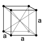
In ccp and hcp lattices, there are two tetrahedral holes per packing atom. A stoichiometry of either M2X or MX2 gives a structure that fills all tetrahedral sites, while an MX structure fills only half of the sites. An example of an MX2 structure is fluorite, CaF2, whose structure is shown in the figure at the left. The packing atom in fluorite is Ca2+ and the structure is composed of three interpenetrating fcc lattices. It should be noted that the Ca2+ ion (gray spheres) as a packing atom defies our "rule" that anions are larger than cations and therefore must be the packing atoms. The fluorite structure is common for ionic MX2 (MgF2, ZrO2, etc.) and M2X compounds (Li2O). In contrast, the hcp relative of the fluorite structure is quite rare because of unfavorable close contacts between like-charged ions.
In terms of geometry, Ca2+ is in cubic coordination with eight F- neighbors, and the fluoride ions are tetrahedrally coordinated by four Ca2+ ions. The 8:4 coordination geometry is consistent with the 1:2 Ca:F stoichiometry; in all crystal structures the ratio of the coordination numbers is the inverse of the stoichiometric ratio. The three interpenetrating fcc lattices have Ca at 0,0,0 , 1/2,1/2,0 , etc....F at 1/4,1/4,1/4 , 3/4,3/4,1/4 , etc... and F at 3/4,3/4,3/4 , 1/4,1/4/3/4 , etc.
Looking more closely at the tetrahedral sites in fluorite, we see that they fall into two distinct groups: T+ and T-. If a tetrahedron is oriented with a vertex pointing upwards along the stacking axis, the site is T+. Likewise, a tetrahedron with a vertex oriented downward is T-. The alternation of T+ and T- sites allows for efficient packing of ions in the structure. The layer stacking sequence in this structure (including fluoride ions in the T+ and T- sites) is:

- ------------ A
- - - -b- - - T+
- - - -a- - - T-
- ------------ B
- - - -c- - - T+
- - - -b- - - T-
- ------------ C
- - - -a- - - T+
- - - -c- - - T-
- ------------ A
- - - -b- - - T+
- - - -a- - - T-
Tetrahedrally bonded compounds with a 1:1 stoichiometry (MX compounds) have only half of the tetrahedral sites (either the T+ or T- sites) filled. In this case, both the M and the X atoms are tetrahedrally coordinated. The zincblende and wurtzite structures are 1:1 tetrahedral structures based on fcc and hcp lattices, respectively. Both structures are favored by p-block compounds that follow the octet rule, and these compounds are usually semiconductors or insulators. The zincblende structure, shown below, can be thought of as two interpenetrating fcc lattices, one of anions and one of cations, offset from each other by a translation of 1/4 along the body diagonal of the unit cell. Examples of compounds with the zincblende structure include CuCl, CuI, ZnSe, HgS, BeS, CdTe, AlP, GaP, SnSb, CSi, and diamond. Additionally, the compound CuInSe2 is zincblende in an ordered, doubled unit cell (the chalcopyrite structure). The solid solution compounds CuIn1-xGaxSe2 with this structure are among the most widely studied materials for use in efficient thin film photovoltaic cells. Using ZnS as a representative of zincblende, the coordination of both Zn and S atoms is tetrahedral. The layer sequence, which is AbBcCaAbBcC..., results in six-membered ZnS rings that have the same geometry as the "chair" version of cyclohexane. The chair conformation allows for a relatively long distance between opposite atoms in the ring and, as a result, it is more sterically favorable than the boat form. The sequence of close-packed layers in zincblende, filling only the T+ sites and leaving the T- sites empty, is shown below:

- ------------ A
- - - -b- - - T+
- - - - - - - T-
- ------------ B
- - - -c- - - T+
- - - - - - - T-
- ------------ C
- - - -a- - - T+
- - - - - - - T-
The wurtzite structure is a close relative of zinc blende, based on filling half the tetrahedral holes in the hcp lattice. Like zincblende, wurtzite contains planes of fused six-membered rings in the chair conformation. Unlike zincblende, however, the rings joining these planes contain six-membered "boat" rings. The boat aligns the anions so that they are directly above the cations in the structure, a less favorable situation sterically but a more favorable one in terms of electrostatics. As a result, the wurtzite structure tends to favor more polar or ionic compounds (e.g., ZnO, NH4+F-) than the zincblende structure. As with zincblende, both ions are in tetrahedral (4:4) coordination and there are typically eight valence electrons in the MX compound. Examples of compounds with this structure include: BeO, ZnO, MnS, CdSe, MgTe, AlN, and NH4F. The layered structure of wurtzite is AbBaAbB and the layer sequence with T+ sites filled is illustrated below:

- ------------ A
- - - -b- - - T+
- - - - - - - T-
- ------------ B
- - - -a- - - T+
- - - - - - - T-
- ------------ A
- - - -b- - - T+
- - - - - - - T-
- ------------ B
An interesting consequence of the layer stacking in the wurtzite structure is that the crystals are polar. When cleaved along the c-axis (the stacking axis), crystals of ZnO, ZnS, and GaN have one negatively charged face and an opposite positively charged face. An applied electric field interacts with the crystal dipole, resulting in compression or elongation of the lattice along this direction. For this reason crystals of compounds in the wurtzite structure are typically piezoelectric.
Some compounds are diamorphic and can have either the zincblende or wurtzite structure. Examples of these compounds that have intermediate polarities include CdS and ZnS. SiO2 exists in polymorphs (crystobalite and tridymite) that resemble zincblende and wurtzite with O atoms midway between each of the Si atoms. The zincblende and wurtzite structures have efficient packing arrangements for tetrahedrally bonded networks and are commonly found in compounds that have tetrahedral bonding. Water, for example, has a tetrahedral hydrogen bonding network and is wurtzite-type. The undistorted wurtzite and zinc blende structures are typically found for AX compounds with eight valence electrons, which follow the octet rule. AX compounds with nine or ten electrons such as GaSe and SbAs crystallize in distorted variants of the wurtzite structure. In GaSe, the extra electrons form lone pairs and this creates layers in the structure, as can be seen in the figure below. To the right of GaSe, the structures of As, Sb, and SbAs show an ever further breakdown of the structure into layers as more valence electrons are added.
-
 Wurtzite crystal structure
 -
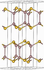 GaSe crystal structure
 -
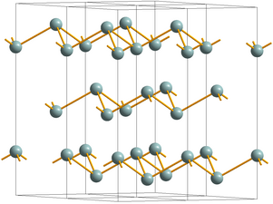 Crystal structure of Sb, SbAs, and gray As
 -
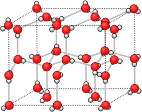 Crystal structure of hexagonal ice
-3D-balls.png)


Hexagonal ice is the most stable polymorph of ice, which is obtained upon freezing at 1 atmosphere pressure. This polymorph (ice-I) has a hcp wurtzite-type structure. Looking at the structure shown at the right, we see that there are irregular arrangements of the O-H---O bonds. In the structure, hydrogen bonding enforces the tetrahedral coordination of each water molecule, resulting in a relatively open structure that is less dense than liquid water. For this reason, ice floats in water.
8.4 Layered structures and intercalation reactions
editLayered structures are characterized by strong (and typically covalent) bonding between atoms in two dimensions and weaker bonding in the third. A broad range of compounds including metal halides, oxides, sulfides, selenides, borides, nitrides, carbides, and allotropes of some pure elements (B, C, P, As) exist in layered forms. Structurally, the simplest of these structures (for example binary metal halides and sulfides) can be described as having some fraction of the octahedral and/or tetrahedral sites filled in the fcc and hcp lattices. For example, the CdCl2 structure is formed by filling all the octahedral sites in alternate layers of the fcc lattice, and the CdI2 structure is the relative of this structure in the hcp lattice.


In the CdCl2 structure, the stacking sequence of anion layers is ABCABC...
In the CdI2 structure, the anion stacking sequence is ABAB..., and all the cations are eclipsed along the stacking axis.
These are examples of 6-3 structures, because the cations are coordinated by an octahedron of six anions, and the anions are coordinated by three cations to make a trigonal pyramid (like NH3). Another way to describe these structures is to say that the MX6 octahedra each share six edges in the MX2 sheets.
Because these structures place the packing atoms (the anions) in direct van der Waals contact, they are most stable for relatively covalent compounds. Otherwise, the electrostatic repulsion between contacting anions would destabilize the structure energetically. More ionic MX2 compounds tend to adopt the fluorite (CaF2) or rutile (TiO2) structures, which are not layered.
Despite the fact that these two structure types are the same at the level of nearest and next-nearest neighbor ions, the CdI2 structure is much more common than the CdCl2 structure.
CdCl2 structure:
- MCl2 (M = Mg, Mn, Fe, Co, Ni, Zn, Cd)
- NiBr2, NiI2, ZnBr2, ZnI2
CdI2 structure:
- MCl2 (M = Ti, V)
- MBr2 (M = Mg, Fe, Co, Cd)
- MI2 (M = Mg, Ca, Ti, V, Mn, Fe, Co, Cd, Ge, Pb, Th)
- M(OH)2 (M = Mg, Ca, Mn, Fe, Co, Ni, Cd)
- MS2 (M = Ti, Zr, Sn, Ta, Pt)
- MSe2 (M = Ti, Zr, Sn, V, Pt)
- MTe2 (M = Ti, Co, Ni, Rh, Pd, Pt)
Physically, layered compounds are soft and slippery, because the layer planes slide past each other easily. For example, graphite, MoS2, and talc (a silicate) are layered compounds that are used widely as lubricants and lubricant additives.
An important reaction of layered compounds is intercalation. In intercalation reactions, guest molecules and ions enter the galleries that separate the sheets, usually with expansion of the lattice along the stacking axis. This reaction is typically reversible if it does not perturb the bonding within the sheets. Often the driving force for intercalation is a redox reaction, i.e., electron transfer between the host and guest. For example, lithium metal reacts with TiS2, MoS2, and graphite to produce LiTiS2, LixMoS2 (x < 1), and LiC6. In these compounds, lithium is ionized to Li+ and the sheets are negatively charged. Oxidizing agents such as Br2, FeCl3, and AsF5 also react with graphite. In the resulting intercalation compounds, the sheets are positively charged and the intercalated species are anionic.

Intercalation reactions are especially important for electrochemical energy storage in secondary batteries, such as lithium ion batteries, nickel-metal hydride batteries, and nickel-cadmium batteries. The reversible nature of the intercalation reaction allows the electrodes to be charged and discharged up to several thousand times without losing their mechanical integrity. In lithium ion batteries, the negative electrode material is typically graphite, which is intercalated by lithium to make LiC6. Several different oxides and phosphates containing redox active transition metal ions (Mn, Fe, Co, Ni) are used as the positive electrode materials.

Lithium ion batteries based on CoO2 were first described in 1980[1] by John B. Goodenough's research group, then at Oxford Univsrsity. In batteries based on CoO2, which has the CdI2 structure, the positive electrode half-reaction is:

The negative electrode half reaction is:

The battery is fully charged when the positive electrode is in the CoO2 form and the negative electrode is in the LiC6 form. Discharge involves the motion of Li+ ions through the electrolyte, forming LixCoO2 and graphite at the two electrodes.


The lithium ion battery is a "rocking chair" battery, so named because charging and discharging involve moving Li+ ions from one side to the other. While the first lithium ion batteries contained layered metal sulfides such as TiS2, metal oxides gave higher operating voltages and more stable batteries. CoO2 is one example of a positive electrode material that has been used in lithium ion batteries. It has a high energy density, but batteries based on CoO2 have poor thermal stability. Safer materials include lithium iron phosphate (LiFePO4), and LiMO2 (M = a mixture of Co, Mn, and Ni). The negative electrode material, LiC6, has a potential close to lithium metal in the electrochemical series. Lithium metal electrodes provide substantially higher energy density than LiC6, but lithium metal batteries are not yet in commercial use because of safety and cycle life issues.[4] Rechargeable lithium ion batteries are used very widely in laptop computers, portable electronics, cellular telephones, cordless tools, and electric and hybrid vehicles. John Goodenough (University of Texas) shared the 2019 Nobel Prize in Chemistry with M. Stanley Whittingham (Binghamton University) and Akira Yoshino (Asahi Kasei) for their foundational research on lithium ion batteries.
A similar intercalation reaction occurs in nickel-cadmium batteries and nickel-metal hydride batteries, except in this case the reaction involves the movement of protons in and out of the Ni(OH)2 lattice, which has the CdI2 structure:

There are many layered compounds that cannot be intercalated by redox reactions, typically because some other stable product is formed. For example, the reaction of layered CdI2 with Li produces LiI (NaCl structure) and Cd metal.
8.5 Bonding in TiS2, MoS2, and pyrite structures
editMany layered dichalcogenides, such as TiS2 and ZrS2, have the CdI2 structure. In these compounds, as we have noted above, the metal ions are octahedrally coordinated by S. Interestingly, the structures of MoS2 and WS2, while they are also layered, are different. In these cases, the metal is surrounded by a trigonal prism of sulfur atoms. NbS2, TaS2, MoSe2, MoTe2, and WSe2 also have the trigonal prismatic molybdenite structure, which is shown below alongside a platy crystal of MoS2.


The coordination of the metal ions by a trigonal prism of chalcogenide ions is sterically unfavorable relative to octahedral coordination. There are close contacts between the chalcogenide ions, which are eclipsed in the stacking sequence AbA/BaB/AbA/BaB... (where "/" indicates the van der Waals gap between layers). What stabilizes this structure?
The molybdenite structure occurs most commonly in MX2 compounds with a d1 or d2 electron count. The figure below compares the splitting of d-orbital energies in the octahedral and trigonal prismatic coordination environments:

The trigonal prismatic structure is stabilized in MoS2 by filling the lowest energy band, the dz2. The dz2 orbital, which points vertically through the triangular top and bottom faces of the trigonal prism, has the least interaction with the sulfide ligands and therefore the lowest energy. The dxz and dyz orbitals, which point at the ligands, have the highest energy. The dz2 orbital is lower in energy in this structure than the t2g orbitals are in the octahedral structure of TiS2.
PtS2, like TiS2, adopts the octahedral CdI2 structure. In this case, because Pt4+ has six d-electrons, the t2g orbitals are filled. There is a large crystal field stabilization energy (which stabilizes the high oxidation state of Pt) because S2- is a strong field ligand. Like MoS2, PtS2 is semiconducting because there is an energy gap between the filled t2g and empty eg bands.
Because it has an unfilled t2g band, TiS2 is relatively easy to reduce by intercalation with Li. For this reason, LiTiS2 was one of the first intercalation compounds studied by Stanley Whittingham, who developed the concept of the non-aqueous lithium ion battery in the early 1970's.[5] Because it has a filled dz2 band, MoS2 is harder to reduce, but it can be intercalated by reaction with the powerful reducing agent n-butyllithium to make LixMoS2 (x < 1). Atoms in the van der Waals planes of these compounds are relatively unreactive, which gives MoS2 its good oxidative stability and enables its application as a high temperature lubricant. Atoms at the edges of the crystals are however more reactive and in fact are catalytic. High surface area MoS2, which has a high density of exposed edge planes, is used as a hydrodesulfurization catalyst and is also of increasing interest as an electrocatalyst for the reduction of water to hydrogen.

Layered metal dichalcogenides, including MoS2, WS2, and SnS2, can form closed nanostructures that take the shape of multiwalled onions and multiwalled tubes. These materials were discovered by the group of Reshef Tenne in 1992, shortly after the discovery of carbon nanotubes. Since then nanotubes have been synthesized from many other materials, including vanadium and manganese oxides.
Although early (TiS2) and late (PtS2) transition metal disulfides have layered structures, a number of MS2 compounds in the middle of the transition series, such as MnS2, FeS2 and RuS2, have three-dimensionally bonded structures. For example, FeS2 has the pyrite structure, which is related to the NaCl structure. The reason is that FeS2 is not Fe4+(S2-)2, but is actually Fe2+(S22-), where S22- is the disulfide anion (which contains a single bond like the peroxide anion O22-). S2- is too strong a reducing agent to exist in the same compound with Fe4+, which is a strong oxidizing agent. Because FeS2 is actually Fe2+(S22-), it is a 1:1 compound and adopts a 1:1 structure.
8.6 Spinel, perovskite, and rutile structures
editThere are three more structures, which are derived from close-packed lattices, that are particularly important because of the material properties of their compounds. These are the spinel structure, on which ferrites and other magnetic oxides are based, the perovskite structure, which is adopted by ferroelectric and superconducting oxides, and the rutile structure, which is a common binary 6:3 structure adopted by oxides and fluorides.


The spinel structure is formulated MM'2X4, where M and M' are tetrahedrally and octahedrally coordinated cations, respectively, and X is an anion (typically O or F). The structure is named after the mineral MgAl2O4, and oxide spinels have the general formula AB2O4.
In the normal spinel structure, there is a close-packed array of anions. The A-site cations fill 1/8 of the tetrahedral holes and the B-site cations fill 1/2 of the octahedral holes. A polyhedral view of the normal spinel unit cell is shown at the left, and a simplified view (with the contents of the back half of the cell removed for clarity) is shown above. Each unit cell contains eight formula units and has a composition A8B16O32.
Inverse spinels have a closely related structure (with the same large unit cell) in which the A-site ions and half of the B-site ions switch places. Inverse spinels are thus formulated B(AB)O4, where the AB ions in parentheses occupy octahedral sites, and the other B ions are on tetrahedral sites. There are also mixed spinels, which are intermediate between the normal and inverse spinel structure.
Some spinel and inverse spinel AB combinations are:
- A2+B3+, e.g., MgAl2O4 (normal spinel)
- A4+B2+, e.g., Pb3O4 = PbII(PbIIPbIV)O4 (inverse spinel)
- A6+B+, e.g., Na2WO4 (normal spinel)
Many magnetic oxides, such as Fe3O4 and CoFe2O4, are spinels.
Normal vs. inverse spinel structure. For transition metal oxide spinels, the choice of the normal vs. inverse spinel structure is driven primarily by the crystal field stabilization energy (CFSE) of ions in the tetrahedral and octahedral sites. For spinels that contain 3d elements such as Cr, Mn, Fe, Co, and Ni, the electron configuration is typically high spin because O2- is a weak field ligand.
As an example, we can consider magnetite, Fe3O4. This compound contains one Fe2+ and two Fe3+ ions per formula unit, so we could formulate it as a normal spinel, Fe2+(Fe3+)2O4, or as an inverse spinel, Fe3+(Fe2+Fe3+)O4. Which one would have the lowest energy?

First we consider the crystal field energy of the Fe2+ ion, which is d6. Comparing the tetrahedral and high spin octahedral diagrams, we find that the CFSE in an octahedral field of O2- ions is [(4)(2/5) - (2)(3/5)]Δo - P = 0.4 Δo - P. In the tetrahedral field, the CFSE is [(3)(3/5) - (3)(2/5)]Δt - P = 0.6 Δt - P. Since Δo is about 2.25 times larger than Δt, the octahedral arrangement has a larger CFSE and is preferred for Fe2+.

In contrast, it is easy to show that Fe3+, which is d5, would have a CFSE of zero in either the octahedral or tetrahedral geometry. This means that Fe2+ has a preference for the octahedral site, but Fe3+ has no preference. Consequently, we place Fe2+ on octahedral sites and Fe3O4 is an inverse spinel, Fe3+(Fe2+Fe3+)O4.
Ferrites are compounds of general formula MIIFe2O4. We can see that magnetite is one example of a ferrite (with M = Fe). Other divalent metals (M = Mg, Mn, Co, Ni, Zn) also form ferrites. Ferrites can be normal or inverse spinels, or mixed spinels, depending on the CFSE of the MII ion. Based on their CFSE, Fe2+, Co2+, and Ni2+ all have a strong preference for the octahedral site, so those compounds are all inverse spinels. ZnFe2O4 is a normal spinel because the small Zn2+ ion (d10) fits more easily into the tetrahedral site than Fe3+ (d5), and both ions have zero CFSE. MgFe2O4 and MnFe2O4, in which all ions have zero CFSE and no site preference, are mixed spinels. Chromite spinels, MIICr2O4, are always normal spinels because the d3 Cr3+ ion has a strong preference for the octahedral site.
Examples of normal and inverse spinel structures:
- MgAl2O4 is a normal spinel since both Mg2+ and Al3+ are non-transition metal ions and thus CFSE = 0. The more highly charged Al3+ ion prefers the octahedral site, where it is surrounded by six negatively charged oxygen atoms.
- Mn3O4 is a normal spinel since the Mn2+ ion is a high spin d5 system with zero CFSE. The two Mn3+ ions are high spin d4 with higher CFSE on the octahedral sites (3/5 ΔO) than on the tetrahedral site (2/5 Δt ~ 1/5 ΔO).
- Fe3O4 is an inverse spinel since the Fe3+ ion is a high spin d5 system with zero CFSE. Fe2+ is a high spin d6 system with more CFSE on an octahedral site than on a tetrahedral one.
- NiFe2O4 is again an inverse spinel since Ni2+ (a d8 ion) prefers the octahedral site and the CFSE of Fe3+ (a d5 ion) is zero.
- FeCr2O4 is a normal spinel since Fe2+ is high spin d6 ion with CFSE = [4(2/5)-2(3/5)] ΔO = 2/5ΔO on an octahedral site, and Cr3+ is a d3 ion with CFSE = 3(2/5) ΔO = 6/5 ΔO. Hence it is more energetically favorable for Cr3+ to occupy both of the octahedral sites.
- Co3O4 is a normal spinel. Even in the presence of weak field oxo ligands, Co3+ is a low spin d6 ion with very high CFSE on the octahedral sites, because of the high charge and small size of the Co3+ ion. Hence the Co3+ ions occupy both octahedral sites, and Co2+ occupies the tetrahedral site.

Magnetism of ferrite spinels. Ferrite spinels are of technological interest because of their magnetic ordering, which can be ferrimagnetic or antiferromagnetic depending on the structure (normal or inverse) and the nature of the metal ions. Fe3O4, CoFe2O4, and NiFe2O4 are all inverse spinels and are ferrimagnets. The latter two compounds are used in magnetic recording media and as deflection magnets, respectively.
In order to understand the magnetism of ferrites, we need to think about how the unpaired spins of metal ions are coupled in oxides. If an oxide ion is shared by two metal ions, it can mediate the coupling of spins by superexchange as shown at the right. The coupling can be antiferromagnetic, as shown, or ferromagnetic, depending on the orbital filling and the symmetry of the orbitals involved. The Goodenough-Kanamori rules predict the local magnetic ordering (ferromagnetic vs. antiferromagnetic) that results from superexchange coupling of the electron spins of transition metal ions. For ferrites, the strongest coupling is between ions on neighboring tetrahedral and octahedral sites, and the ordering of spins between these two sites is reliably antiferromagnetic.

Because all the tetrahedral and octahedral sites in a spinel or inverse spinel crystal are coupled together identically, it works out that ions on the tetrahedral sites will all have one orientation (e.g., spin down) and ions on all the octahedral sites will have the opposite orientation (e.g., spin up). If the number of spins on the two sites is the same, then the solid will be antiferromagnetic. However, if the number of spins is unequal (as in the case of Fe3O4, CoFe2O4, and NiFe2O4) then the solid will be ferrimagnetic. This is illustrated at the left for Fe3O4. The spins on the Fe3+ sites cancel, because half of them are up and half are down. However, the four unpaired electrons on the Fe2+ ions are all aligned the same way in the crystal, so the compound is ferrimagnetic.

Perovskites are ternary oxides of general formula ABO3. More generally, the perovskite formula is ABX3, where the anion X can be O, N, or halogen. The A ions are typically large ions such as Sr2+, Ba2+, Rb+, or a lanthanide 3+ ion, and the B ions are smaller transition metal ions such as Ti4+, Nb5+, Ru4+, etc. The mineral after which the structure is named has the formula CaTiO3.
The perovskite structure has simple cubic symmetry, but is related to the fcc lattice in the sense that the A site cations and the six O atoms comprise a fcc lattice. The B-site cations fill 1/4 of the octahedral holes and are surrounded by six oxide anions.

The coordination of the A ions in perovskite and the arrangement of BO6 octahedra is best understood by looking at the ReO3 structure, which is the same structure but with the A-site cations removed. In the polyhedral representation of the structure shown at the right, it can be seen that the octahedra share all their vertices but do not share any octahedral edges. This makes the ReO3 and perovskite structures flexible, like three-dimensional wine racks, in that the octahedra can rotate and tilt cooperatively. Eight such octahedra surround a large cuboctahedral cavity, which is the site of the A ions in the perovskite structure. Cations in these sites are coordinated by 12 oxide ions, as expected from the relationship between the perovskite and fcc lattices.
Because the A-site is empty in the ReO3 structure, compounds with that structure can be reversibly intercalated by small ions such as Li+ or H+, which then occupy sites in the cuboctahedral cavity. For example, smart windows that darken in bright sunlight contain the electrochromic material WO3, which has the ReO3 structure. In the sunlight, a photovoltaic cell drives the reductive intercalation of WO3 according to the reaction:

WO3 is a light yellow compound containing d0 W(VI). In contrast, HxWO3, which is mixed-valent W(V)-W(VI) = d1-d0, has a deep blue color. Such coloration is typical of mixed-valence transition metal complexes because their d-electrons can be excited to delocalized conduction band levels by red light. Because the electrochemical intercalation-deintercalation process is powered by a solar cell, the tint of the windows can adjust automatically to the level of sunlight.

Ferroelectric perovskites. The flexibility of the network of corner-sharing BO6 octahedra is also very important in ferroelectric oxides that have the perovskite structure. In some perovsites with small B-site cations, such as Ti4+ and Nb5+, the cation is too small to fit symmetrically in the BO6 octahedron. The octahedron distorts, allowing the cation to move off-center. These distortions can be tetragonal (as in the example shown at the right), rhombohedral, or orthorhombic, depending on whether the cation moves towards a vertex, face, or edge of the BO6 octahedron. Moving the cation off-center in the octahedron creates an electric dipole. In ferroelectrics, these dipoles align in neighboring unit cells through cooperative rotation and tilting of octahedra. The crystal thus acquires a net electrical polarization.
Ferroelectricity behaves analogously to ferromagnetism, except that the polarization is electrical rather than magnetic. In both cases, there is a critical temperature (Tc) above which the spontaneous polarization of the crystal disappears. Below Tc, the electric polarization of a ferroelectric can be switched with a coercive field, and hysteresis loop of polarization vs. field resembles that of a ferromagnet. Above Tc, the crystal is paraelectric and has a high dielectric permittivity.
Ferroelectric and paraelectric oxides (along with piezoelectrics and pyroelectrics) have a wide variety of applications as switches, actuators, transducers, and dielectrics for capacitors. Ferroelectric capacitors are important in memory devices (FRAM) and in the tuning circuits of cellular telephones. Multiferroics, which are materials that are simultaneously ferroelectric and ferromagnetic, are rare and are being now intensively researched because of their potential applications in electrically adressable magnetic memory.

Halide perovskites (ABX3, X = Cl, Br, I) can be made by combining salts of monovalent A ions (A+ = Cs+, NH4+, RNH3+) and divalent metal salts such as PbCl2 or PbI2. These compounds have sparked recent interest as light absorbers for thin film solar cells that produce electricity from sunlight. Lead and tin halide perovskites can be grown as thin films from solution precursors or by thermal evaporation at relatively low temperatures. In some lead halide perovskites, the mobility of electrons and holes is very high, comparable to that of more expensive III-V semiconductors such as GaAs, which must be grown as very pure single crystals at high temperatures for use in solar cells. Because of their high carrier mobility, some lead halide perovskites are also electroluminescent and are of interest as inexpensive materials for light-emitting diodes (LEDs).

Tin and lead halide perovskites were first studied in the 1990s as materials for thin film electronics,[6] and more recently as light absorbers in dye-sensitized solar cells. Soon after the results on dye-sensitized perovskite cells were reported, it was discovered that halide perovskites could also be used in thin film solid state solar cells. The structures of these solar cells are shown schematically at the right. The highest reported solar power conversion efficiencies of perovskite solar cells have jumped from 3.8% in 2009 [7] to 10.2% in 2012[8] to 25.5% in 2020 in single-junction architectures,[9] and, in silicon-based tandem cells, to 29.15%,[9] exceeding the maximum efficiency achieved in single-junction silicon solar cells. Perovskite solar cells are therefore the fastest-advancing solar technology. With the potential of achieving even higher efficiencies and very low production costs, perovskite solar cells have become commercially attractive. The highest performing cells to date contain divalent lead in the perovskite B cation site and a mixture of methylammonium and formamidinium ions in the perovskite A cation site.
Despite their very impressive efficiency, perovskite solar cells are less stable than solar cells made from covalent network solids such as Si or GaAs, and are sensitive to air and moisture. Current research is focused on understanding the degradation mechanisms of these solar cells and improving their stability under operating conditions.


The rutile structure is an important MX2 (X = O, F) structure. It is a 6:3 structure, in which the cations are octahedrally coordinated by anions, and as such is intermediate in polarity between the CaF2 (8:4) and SiO2 (4:2) structures. The mineral rutile is one of the polymorphs of TiO2, the others (anatase and brookite) also being 6:3 structures.
The rutile structure can be described as a distorted version of the NiAs structure with half the cations removed. Recall that compounds with the NiAs structure were typically metallic because the metal ions are eclipsed along the stacking axis and thus are in relatively close contact. In rutile, the MO6 octahedra share edges along the tetragonal c-axis, and so some rutile oxides, such as NbO2, RuO2 and IrO2, are also metallic because of d-orbital overlap along that axis. These compounds are important as electrolyzer catalysts and catalyst supports because they combine high catalytic activity with good electronic conductivity.
Rutile TiO2, because of its high refractive index, is the base pigment for white paint. It is a wide bandgap semiconductor that has also been extensively researched as an electrode for water splitting solar cells and as a photocatalyst (primarily as the anatase polymorph) for degradation of pollutants in air and water. Self-cleaning glass exploits the photocatalytic properties of a thin film of TiO2 to remove oily substances from the glass surface and improve the wetting properties of the glass.
8.7 Discussion questions
edit- Using the Liverpool 3D visualization website (http://www.chemtube3d.com/solidstate/_table.htm) determine the anion and cation coordination geometries in cadmium chloride and anatase. Describe the arrangement of octahedra (in terms of whether they share edges, faces, etc.) in these structures.
- Count the number of atoms in the Li3Bi and ReO3 unit cells, and determine the coordination environments of each of the ions.
- Silicon, germanium, and many other semiconductors adopt the diamond (or zincblende) structure. Assuming that all the atoms are the same size, calculate the volume fraction of the unit cell that is occupied by the atoms. How does the filling fraction of diamond compare to simple cubic and close-packed structures, and what does this tell us about the relationship between coordination number and density?
- Describe the structural basis of ferroelectricity in barium titanate.
8.8 Problems
edit1. For each of the following close packed layer sequences, indicate the name of the structure (structure type), the coordination environment of the cations (represented by lower case letters), and the coordination environment of the anions (upper case letters). Give two additional examples (apart from the structure type itself) of compounds with the same structure.
(a) AbBaAbBaAbB......
(b) AaBbCcAaBbCc.....
(c) AcBaCbAcBaCb.....
(d) AcB | AcB | AcB |.... ("|" = van der Waals gap)
2. Below are sections of the lithium oxide unit cell.

(a) Describe how to obtain (and do obtain) the empirical formula.
(b) What is the coordination number and geometry for each type of ion?
(c) Which atom is close-packed?
(d) What type and fraction of holes are filled by the other ion?
3. The hexagonal unit cell of a metal nitride is shown below in sections.

(a) What is the empirical formula of the compound?
(b) How many M atoms are coordinated to each N atom?
(c) In what group of the periodic table would you expect to find M?
4. Draw the cubic Li3Bi unit cell in sections.
5. If half the cesium is removed from the CsCl structure, such that each Cl atom is then tetrahedrally coordinated, what structure type is generated?
6. The crystal structure of a certain ternary oxide is shown below.

(a) What is the empirical formula, and how many formula units are in the unit cell?
(b) Which atoms (if any) are close packed?
(c) How many oxide ions coordinate each of the different cations in the structure?
(d) Are the coordination numbers in part (c) different? If so, why?
7. The structures of the disulfides (MS2) show an apparently unusual trend, proceeding from left to right across the transition series. On the left side (TiS2, ZrS2, MoS2, etc.), one finds layered structures, whereas in the middle (ReS2, FeS2, RuS2) there are three-dimensional pyrite- and marcasite-type structures. On the right (PtS2, SnS2), there are again layered structures. Briefly explain these trends.
8. Explain why layered compounds are typically covalent and rarely ionic.
9. Draw the zincblende structure in sections.
10. The zincblende structure is rarely found with very polar or ionic compounds. However, some polar and ionic compounds (BeO, NH4F, etc.) have the wurtzite structure.
(a) Describe the similarities and the differences between the zincblende and wurtzite structures (in terms of coordination numbers, stacking sequence of cations and anions, etc.) (b) Why is wurtzite more ionic than zincblende?
11. A recent article by R. Cava and co-workers (Nature Materials 2010, 9, 546-9) describes the unusual electronic properties of a Y-Pt-Bi alloy, the structure of which is shown in sections below:

(a) What is the stoichiometry of the compound?
(b) How many Y and how many Pt atoms coordinate each Bi atom?
12. The fluorite structure, CaF2, which is generated by filling all the tetrahedral holes in a FCC array, is a common MX2 structure type.
(a) What is the coordination environment of F in a hypothetical relative of CaF2, in which Ca forms a hcp array and F occupies all the tetrahedral sites?
(b) Suggest a reason why the structure described in (a) is very rare.

13. The cuprite (Cu2O) structure is related to zincblende (or diamond) in that oxygen occupies both the Zn and S positions, with copper in between. This is shown schematically at the right. Actually, in cuprite there are two such interpenetrating networks with no bonds between them. Draw the second network in the empty cell. If you put the two halves together and take out the copper, what cubic packing lattice do you get? Is it a closest packing lattice?
(Hint #1: start with an O atom at 1/2,1/2,1/2) (Hint #2: try this in pencil first)
14. Draw the rutile structure in sections of the unit cell, and verify that the stoichiometry is MX2. What are the coordination numbers of Ti and O?
15. Stishovite is a high pressure form of SiO2 found in meteorite craters. While normal SiO2 has the quartz structure, in which each Si is coordinated by four O atoms, stishovite has the rutile structure. Would you expect the Si-O bond to be longer in stishovite, or in quartz? What is the bond order in each polymorph?
16. Na and Cl combine in a 1:1 ratio to make the ionic NaCl lattice. Interestingly, recent theoretical predictions (confirmed by high pressure synthesis and crystallography) have identified several other stoichiometries that form stable crystals at high pressure. These include Na3Cl, Na2Cl, Na3Cl2, NaCl3, and several others.[10] The structure of one of these new sodium chlorides is shown below in sections.

- a) What is the stoichiometry of this compound?
- b) What are the coordination numbers of Na and Cl, and how do they compare to the coordination numbers in NaCl and Na metal?
- c) Based on your answer to (b), explain why high pressure should stabilize this phase.
17. One of the new compounds discovered in the study described in problem 16 is NaCl3. There are two polymorphs of this compound, one of which contains linear Cl3- ions. Accurate molecular orbital calculations indicate that the charge on the central Cl atom in these linear anions is close to zero. Draw the MO diagram and the valence bond pictures for the Cl3- ion that are consistent with these observations. Would you expect the Cl-Cl bond to be longer or shorter than the bond in Cl2?
18. Some MX salts can exist in either the CsCl or NaCl structure. Use the Pauling formula to predict the M-X bond length in the CsCl structure of a compound that has a bond length of 3.5 Å in the NaCl structure. Would applying a high pressure stabilize the CsCl form, or the NaCl form of this compound? (hint: calculate the volume per formula unit)
19. Mn3O4 and Fe3O4 are both mixed-valence oxides. In both cases, there is one M2+ ion and two M3+ ions per formula unit (M = Fe, Mn).
- (a) One of these is a normal spinel and one is an inverse spinel. Explain which is which, and why. (hint: think about CFSE's)
- (b) For Mn3O4, what kind of magnetic ordering (ferri-, ferro-, or antiferromagnetic) would you expect, and why? You can assume that neighboring tetrahedral and octahedral ions in the structure are antiferromagnetically coupled.
- (c) Sketch the approximate form of the χ vs. T and 1/χ vs. T curves for Mn3O4. Label any special values of temperature on your graphs.
20. Predict whether each of the following should form a normal or inverse spinel: MgV2O4, VMg2O4, NiGa2O4, ZnCr2S4, NiFe2O4. Would kind of magnetic ordering (ferro-, ferri-, or antiferromagnetic) would you predict for NiFe2O4?
21. For each pair, which structure is preferred by LESS polar compounds?
A. NaCl CsCl
B. Zincblende Wurtzite
C. CdI2 CdCl2
D. NaCl NiAs
E. Fluorite Quartz (SiO2)
22. For the following inorganic crystal structures, describe the arrangement of packing ions and interstitial ions, give the layer stacking sequence (such as AaBbCcA...), and draw the unit cell in sections.
A. Zincblende
B. Wurtzite
8.9 References
edit- ↑
K. Mizushima, P.C. Jones, P.J. Wiseman, J.B. Goodenough (1980). "LixCoO2 (0<x<l): A New Cathode Material for Batteries of High Energy Density". Materials Research Bulletin. 15: 783–789. doi:10.1016/0025-5408(80)90012-4.
{{cite journal}}: CS1 maint: multiple names: authors list (link) - ↑ Yang Shao-Horn, Laurence Croguennec, Claude Delmas, E. Chris Nelson and Michael A. O'Keefe (July 2003). "Atomic resolution of lithium ions in LiCoO2". Nature Materials. 2 (7): 464–467. doi:10.1038/nmat922. PMID 12806387.
{{cite journal}}: CS1 maint: multiple names: authors list (link) - ↑ M.S. Whittingham (1976). "Electrical Energy Storage and Intercalation Chemistry". Science. 192: 1126–1127. doi:10.1126/science.192.4244.1126.
- ↑
. Gao, Z. Yan, J. L. Gray, X. He, T. Chen, Q. Huang, Y. C. Li, H. Wang, S. H. Kim, T. E. Mallouk, and D. Wang (2019). "Polymer–inorganic solid–electrolyte interphase for stable lithium metal batteries under lean electrolyte conditions". Nature Materials. 18: 384–389. doi:10.1038/s41563-019-0305-8.
{{cite journal}}: CS1 maint: multiple names: authors list (link) - ↑ M. Stanley Whittingham "Lithium Batteries and Cathode Materials" Chem. Rev., 2004, vol. 104, pp. 4271–4302. DOI: 10.1021/cr020731c
- ↑ Kagan, Cherie R.; Mitzi, David B.; Dimitrakopoulos, C. D. (1999). "Organic-inorganic hybrid materials as semiconducting channels in thin-film field-effect transistors". Science. 286: 945–947. doi:10.1126/science.286.5441.945.
{{cite journal}}: Cite has empty unknown parameter:|1=(help) - ↑ Kojima, Akihiro; Teshima, Kenjiro; Shirai, Yasuo; Miyasaka, Tsutomu (6 May 2009). "Organometal Halide Perovskites as Visible-Light Sensitizers for Photovoltaic Cells". Journal of the American Chemical Society. 131 (17): 6050–6051. doi:10.1021/ja809598r. PMID 19366264.
- ↑ Chung, In; Lee, Byunghong; He, Jiaking; Chang, Robert P. H.; Kanatzidis, Mercouri G. (24 May 2012). "All-solid-state dye-sensitized solar cells with high efficiency". Nature. 485: 486–489. doi:10.1038/nature11067.
- ↑ a b "NREL efficiency chart" (PDF).
- ↑ W. Zhang et al. (2013), "Unexpected Stable Stoichiometries of Sodium Chlorides." Science, vol. 342, no. 6165, pp. 1502-1505. doi: 10.1126/science.1244989