Fire Simulation for Engineers/FDS/Solid Geometry
Solid geometry
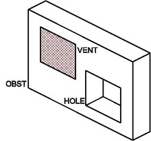
editFourth, the solid geometry is entered via OBST, VENT, HOLE namelist groups.
A considerable amount of work in setting up a calculation lies in specifying the geometry of the space to be modeled and applying boundary conditions to these objects. The geometry is described in terms of obstructions to the gas phase flow. A boundary condition needs to be assigned to each bounding surface of the gas phase domain describing its thermal properties. Both solid obstruction faces and the exterior boundaries of the computational domain need a boundary condition assigned. A fire is just one type of boundary condition.
Defining solid obstructions, OBST
editThe namelist group OBST contains parameters used to define obstructions. Each OBST line define a solid volume within the computational domain.
The boundary condition for whole faces of the obstruction can be easily specified prescribing one of the following three parameters: SURF_ID, SURF_IDS, or SURF_ID6.
The parameter SURF_ID designates one SURF boundary condition to apply to all the faces of the obstruction. For example:
&OBST XB=2.3,4.5,1.3,4.8,0.0,9.2, SURF_ID='brick wall' /
builds a solid obstruction and apply the brick wall surface type to all its six faces.
If the obstruction has different properties for its top, sides and bottom, use instead the parameter SURF_IDS, an array of three character strings specifying the boundary condition for the top, sides and bottom of the obstruction, respectively. For example:
 &OBST XB=2.3,4.5,1.3,4.8,0.0,9.2,
     SURF_IDS='burner','brick wall','INERT' /
builds a solid obstruction and applies the burner surface type to the top face (+z direction), brick wall surface type to sides, and INERT surface type to the bottom face (-z direction).
If the obstruction has different properties for all its faces, use instead the parameter SURF_ID6, an array of six character strings specifying the boundary condition for each face. For example:
 &OBST XB=2.3,4.5,1.3,4.8,0.0,9.2,
     SURF_ID6='bc-x','bc+x','bc-y','bc+y','bc-z','bc+z' /
builds a solid obstruction and applies:
• the bc-x surface type to the x=2.3 face (face in -x direction),
• the bc+x surface type to the x=4.5 face (face in +x direction),
• the bc-y surface type to the y=1.3 face (face in -y direction),
• the bc+y surface type to the y=4.8 face (face in +y direction),
• the bc-z surface type to the z=0.0 face (face in -z direction),
• the bc+z surface type to the z=9.2 face (face in +z direction).
Note that SURF_ID6 complies to the same convention as the XB parameter.
The following table summarizes some OBST parameters:
| Parameter | Type | Description | Unit | Default |
|---|---|---|---|---|
| XB(6) | Real | Volume | m | |
| SAWTOOTH | Logical | Sawtooth | .TRUE. | |
| THICKEN | Logical | Force at least one cell thick | .FALSE. | |
| SURF_ID | String | Set boundary conditions (all faces) | 'INERT' | |
| SURF_IDS(3) | String | Set boundary conditions (top, side, bottom faces) | 'INERT' | |
| SURF_IDS(6) | String | Set boundary conditions (each of six faces) | 'INERT | |
| ALLOW_VENT | Logical | Allow VENT on OBST | .TRUE. | |
| PERMIT_HOLE | Logical | Allow OBST to be carved by a HOLE | .TRUE. | |
| COLOR | String | Color | ||
| RGB(3) | Integer | Color | 255,204,102 | |
| TRANSPARENCY | Real | Transparency | 1 | |
| OUTLINE | Logical | Draw as outline in Smokeview | .TRUE. | |
| DEVC_ID | String | ID of DEVC that controls OBST's existence | ||
| CTRL_ID | String | ID of CTRL that controls OBST's existence |
Creating voids inside obstructions, HOLE
editThe HOLE namelist group is used to carve a hole out of an existing obstruction or set of obstructions. To do this, add lines of the form:
&HOLE XB=2.0,4.5,1.9,4.8,0.0,9.2 /
Any solid mesh cells within the volume 2.0<x<4.5, 1.9<y<4.8, 0.0<z<9.2 are removed. Obstructions intersecting the volume are broken up into smaller blocks.
If the hole represents a door or window, a good rule of thumb is to punch more than enough to create the hole. This ensures that the hole is created through the entire obstruction. For example:
 &OBST XB=1.0,1.1,0.0,5.0,0.0,3.0 /
 &HOLE XB=0.99,1.11,2.0,3.0,0.0,2.0 /
the OBST line denotes a wall 0.1 m thick; the HOLE line creates a door. The extra centimeter added to the x coordinates of the hole make it clear that the hole is to punch through the entire obstruction.
If an obstruction is not to be punctured by a HOLE, add the parameter PERMIT_HOLE=.FALSE. to the OBST line.
Note that a HOLE has no effect on a VENT or a mesh boundary. It only applies to obstructions.
The following table summarizes some HOLE parameters:
| Parameter | Type | Description | Unit | Default |
|---|---|---|---|---|
| XB(6) | Real | Volume, cutout | m | |
| COLOR | String | Color for resulting obstruction | ||
| RGB(3) | Integer | Color for resulting obstruction | ||
| TRANSPARENCY | Real | Transparency of resulting obstruction | ||
| DEVC_ID | String | ID of DEVC that controls HOLE's existence | ||
| CTRL_ID | String | ID of CTRL that controls HOLE's existence |
Prescribing a different boundary condition, VENT
editOBST namelist group can easily prescribe boundary conditions of entire faces of obstacles. But very often you will need to apply a particular boundary condition to a rectangular patch of an entire face or to the exterior boundaries of the computational domain.
The VENT namelist group is used to prescribe these particular boundary conditions:
• on flat faces adjacent to obstructions,
• or exterior boundaries of the computational domain.
For example, the lines:
 &VENT XB=1.0,2.0,2.0,2.0,1.0,3.0, SURF_ID='burner' /
 &OBST XB=0.0,5.0,2.0,3.0,0.0,4.0, SURF_ID='brick wall' /
build a solid obstacle made of brick wall and apply a burner boundary condition to a rectangular patch on the solid face in -y direction.
To set boundary conditions to exterior boundaries of the computational domain proceed as in the following example:
!!! Computational domain
&MESH IJK=32,32,16, XB=0.0,1.6,0.0,1.6,0.0,0.8 /
&MESH IJK=32,32,16, XB=0.0,1.6,0.0,1.6,0.8,1.6 /
!!! Properties
&SURF ID='brick wall', COLOR='BROWN' /
&SURF ID='floor', COLOR='SILVER' /
&SURF ID='ceiling', COLOR='SLATE GRAY' /
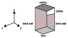
!!! Solid geometry
&VENT XB=0.0,0.0,0.0,1.6,0.0,1.4, SURF_ID='brick wall' /
lower part of -x exterior boundary
&VENT XB=0.0,0.0,0.0,1.6,1.4,1.6, SURF_ID='OPEN' /
upper part of -x exterior boundary
&VENT XB=1.6,1.6,0.0,1.6,0.0,1.6, SURF_ID='OPEN' /
+x exterior boundary
&VENT XB=0.0,1.6,0.0,0.0,0.0,1.6, SURF_ID='brick wall' /
-y exterior boundary
&VENT XB=0.0,1.6,1.6,1.6,0.0,1.6, SURF_ID='OPEN' /
+y exterior boundary
&VENT XB=0.0,1.6,0.0,1.6,0.0,0.0, SURF_ID='floor' /
-z exterior boundary
&VENT XB=0.0,1.6,0.0,1.6,1.6,1.6, SURF_ID='ceiling' /
+z exterior boundary
The result is shown in Figure [fig:Setting-exterior-boundaries].
A shortcut exists to select mesh boundaries: the MB parameter. This manual will not cover it because it leads to error and confusion when employed with multiple meshes.
Note that:
• Only one VENT may be specified for any given wall cell. If additional VENT lines are specified for a given wall cell, FDS will output a warning message and ignore the subsequent lines. The first defined VENT will be applied: first-come, first-served.
• VENT overrides the boundary condition defined by the underlying obstruction: VENT boundary condition wins on OBST boundary condition.
• A VENT must always be attached to a solid obstruction or exterior boundaries of the computational domain: a flying VENT is not allowed.
• If FDS outputs an error message requesting that the orientation of a VENT be specified, check to make sure that the VENT is a plane and that it is not buried within a solid obstruction.
The following table summarizes some VENT parameters:
| Parameter | Type | Description | Unit | Default |
|---|---|---|---|---|
| XB(6) | Real | Face | m | |
| PBX, PBY, PBZ | Real | Plane | m | |
| IOR | Integer | Index of orientation | ||
| SURF_ID | String | Set boundary condition | 'INERT' | |
| DEVC_ID | String | ID of DEVC that controls VENT's existence | ||
| CTRL_ID | String | ID of CTRL that controls VENT's existence |
Default boundary condition
editINERT is the default SURF boundary condition for all solid surfaces and the exterior boundary of the computational domain, if not otherwise specified.
If you want to change the default boundary condition, set SURF_DEFAULT parameter on the MISC line. For example:
&MISC SURF_DEFAULT='steel' /
If the default boundary condition is desired for the faces of an obstruction, then SURF_ID* need not be set. For example:
&OBST XB=2.3,4.5,1.3,4.8,0.0,9.2 /
builds a solid obstruction and apply the default surface type to all its faces.
The same is true for a VENT:
&VENT XB=2.3,4.5,1.3,4.8,0.0,0,0 /
How thick is a wall?
editThe lines:
 &MATL ID='brick', CONDUCTIVITY=0.69, SPECIFIC_HEAT=0.84,
     DENSITY=1600. / material
 &SURF ID='brick wall', MATL_ID(1,1)= 'brick', THICKNESS= 0.1 /
     boundary condition
 &OBST XB=0.,10.,0.,.2,0.0,2.7, SURF_ID='brick wall' /
     solid obstruction
first define a brick material and describe a brick wall boundary condition, then build a solid obstruction applying the brick wall surface type to all its faces.
If you carefully examine the prescriptions:
• The OBST object is 10 m long, 2.7 m high, and 0.2 m thick in the y direction.
• The brick wall boundary condition (SURF line) prescribe a 0.1 m thicknesses for the same wall.
At first sight, these two parameters seem in contradiction.
But, if you remember what was anticipated in Section [sec:Each-model-its-data], the THICKNESS parameter indicated by the SURF line, does not need to match the XB dimensions of the solid obstruction prescribed by OBST.
In fact, the two parameters are independent from each other:
• The OBST line describes the overall geometric structure of a solid that obstacles the gas phase flow: it provides data to the hydrodynamic model.
• The SURF line describes the characteristics of the surfaces of the solid, used to provide a reasonable bounding surface temperature for the gas phase calculation: it provides data to the solid heat transfer model.
When a SURF boundary condition is applied to the faces of a solid obstruction, FDS performs a separate one-dimensional heat transfer calculation at each face of the solid, using the THICKNESS parameter. There is no communication among the faces.
Obviously, this is not an ideal way to perform solid phase heat transfer, but that's currently beyond FDS scope!
Thin sheet obstructions
editObstructions can be flat. Often, thin sheets, like a window, form a barrier, but if the numerical mesh is coarse relative to the thickness of the barrier, the obstruction might be unnecessarily large if it is assumed to be one layer of mesh cells thick.
All faces of an obstruction are shifted to the closest mesh cell. If the obstruction is very thin, the two faces may be approximated on the same cell face.
FDS and Smokeview render this obstruction as a thin sheet, but it is allowed to have thermally thick boundary conditions, in other words a not null THICKNESS of the applied SURF.
A thin sheet obstruction can only have one velocity vector on its face, thus a gas cannot be injected reliably from a thin obstruction because whatever is pushed from one side is necessarily pulled from the other. For full functionality, the obstruction should be specified to be at least one mesh cell thick.
Thin sheet obstructions work fine as flow barriers, but other features are fragile and should be used with caution.
To prevent FDS from allowing thin sheet obstructions, set THICKEN_OBSTRUCTIONS=.TRUE. on the MISC line, or THICKEN=.TRUE. on each OBST line for which the thin sheet assumption is not allowed.
Activating and deactivating objects
editBy default the objects and their prescribed boundary conditions are activated and come to existence when the calculation starts, then they are deactivated and disappear when the calculation ends.
If needed, activation and deactivation times of single OBST, VENT and HOLE can be prescribed by a control logic, as explained in Chapter [cha:Devices-and-control-logic].
Stair stepping complex geometries
editThe efficiency of FDS is due to the simplicity of its numerical mesh. However, there are situations in which certain geometric features do not conform to the rectangular mesh, such as a sloped ceiling or roof. In these cases, construct the curved geometry using rectangular obstructions, a process sometimes called stair stepping.
A concern is that the stair stepping changes the flow pattern near the wall. To lessen the impact of stair stepping on the flow field near the wall, prescribe the parameter SAWTOOTHSAWTOOTH=.FALSE. on each OBST line that makes up the stair stepped obstruction. The effect of this parameter is to prevent vorticity from being generated at sharp corners, in effect smoothing out the jagged steps that make up the obstruction.
For example, the lines:
 &OBST XB=0.00, 0.05,-0.01, 0.01, 0.00, 0.05,
     SAWTOOTH=.FALSE., COLOR='GREEN' /
 &OBST XB=0.05, 0.10,-0.01, 0.01, 0.00, 0.10,
     SAWTOOTH=.FALSE., COLOR='GREEN' /
 &OBST XB= 0.10, 0.15,-0.01, 0.01, 0.05, 0.15,
     SAWTOOTH=.FALSE., COLOR='GREEN' /
 ...
 &OBST XB=0.00, 0.05,-0.01, 0.01, 0.05, 0.10,
     SAWTOOTH=.TRUE., COLOR='TEAL' /
 &OBST XB=0.05, 0.10,-0.01, 0.01, 0.10, 0.15,
     SAWTOOTH=.TRUE., COLOR='TEAL' /
 &OBST XB=0.10, 0.15,-0.01, 0.01, 0.15, 0.20,
     SAWTOOTH=.TRUE., COLOR='TEAL' /
 ...
create a two sided oblique wall. The resulting flow is shown in Figure [fig:SAWTOOTH].

This is not a complete solution of the problem, but it does provide a simple way of ensuring that the flow field around a non-rectangular obstruction is not inhibited by extra drag created at sharp corners.
Coloring individual objects
editObjects may be colored individually, overriding SURF prescription, by specifying a COLOR or RGB value on the respective OBST or VENT line:
&OBST XB=..., SURF_ID='carpet', COLOR='INDIGO' /
This is not recommended. As explained in Section [sec:Coloring-boundary-conditions], it is much better to assign a color to each boundary condition.
Making burning solids disappear
editIf a burning object is to disappear from the calculation once it is consumed, set BURN_AWAYBURN_AWAY=.TRUE. on the corresponding SURF line. The solid object disappears from the calculation cell by cell, as the mass contained by each mesh cells is consumed either by the pyrolysis reactions or by the prescribed HRR. The mass of each mesh cell is the cell face area multiplied by the surface density of the SURF type.
An example:
 &SURF ID='stuff', MATL_ID(1:2,1)='fabric','foam',
     THICKNESS(1:2)=0.01,0.1, BURN_AWAY=.TRUE. /
Keep in mind the following issues:
• For reacting surfaces, the surface density is computed as a sum of the layer densities multiplied by the layer thicknesses. This value can be overridden by setting SURFACE_DENSITY on the SURF line.
• For surfaces with prescribed HRRPUA, add SURFACE_DENSITY parameter as this is the only way of defining the mass of the object.
• Use BURN_AWAY parameter cautiously. If an object has the potential of burning away, a significant amount of extra memory has to be set aside to store additional surface information as the rectangular block is eaten away.
• If BURN_AWAY is prescribed, the SURF should be applied to the entire object, not just to a face of the object, because it would be unclear how to handle edges of solid obstructions that have different SURF_IDs on different faces.
See [FDS5 user's guide] for broader discussion on the topic.