Computer network technologies and services/Migration to IPv6
Introduction
editDuring the migration phase, hosts should gradually start being able to reach IPv6 destinations while keeping being able to reach IPv4 destinations. Migrating all network devices is a condition needed but not sufficient: the user needs to make them work together by making a new addressing plan for the whole network.
Migrating hosts
editMigrating applications
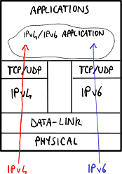
editIntroducing IPv6 support into applications results in need to change the source code:
- servers: the running process on a server should open two threads, one on listening to the IPv4 socket and another one on listening to the IPv6 socket, in order to be able to serve both IPv4 and IPv6 requests;
- clients: applications such as web browsers should be able to print in output and get in input addresses in the new format.
Migrating operating systems
edit-
 Dual stack without dual layer.
 -
 Dual stack with dual layer.


Applications lie mostly on the operating system libraries, which can introduce IPv6 support by adopting the dual stack approach:
- without dual layer: the operating system processes independently IPv4 and IPv6 addresses → the software should be able to manage both IPv4 and IPv6 addresses;
- with dual layer: the operating system is able to convert an IPv4 address into an IPv4-mapped IPv6 address → the software can just support IPv6 addresses without caring of IPv4 addresses.
The variant with dual layer is the most used one because it moves the complexity to the core of the operating system.
Migrating network devices
editMigrating switches
editAlthough in theory switches should be not affected at all by changes at layer 3 because they work up to the layer 2, there could be some troubles with additional functions: for example IGMP snooping, a functionality used to filter incoming multicast packets, needs to look inside the packet → as the packet format and fields change the switch can not recognize the multicast IPv6 packets and it discards them.
Migrating routers
editNowadays routers are mostly ready for IPv6, even if performance in IPv6 is still worse than the one in IPv4 because of lack of experience and lower traffic demand.
Tipically routers supporting IPv6 adopt the dual stack 'ships in the night'-like approach: IPv4 and IPv6 are supported by two independent stacks for transport layer → this requires the complete duplication for all components: routing protocols, routing tables, access lists, etc.
Routing tables
editRouting in IPv6 is performed in the same way as IPv4 but it requires two distinct routing tables, one for IPv4 routes and another for IPv6 routes. IPv6 routing tables can store several types of entries, including:
- indirect entries (O/S codes): they specify the addresses, typically link local, of the interfaces of the next-hop routers to which to send packets addressed towards remote links;
- direct entries: they specify the interfaces of the router itself through which to send packets addressed towards local links:
- connected networks (C code): they specify the prefixes of the local links;
- interface addresses (L code): they specify the interface identifiers in the local links.
Routing protocols
editRouting protocols supporting IPv6 can adopt two approaches:
- integrated routing (e.g. BGP): the protocol allows to exchange both IPv4 and IPv6 routing information at the same time → IPv4 and IPv6 addresses belonging to the same destination can be transported via a single message → higher efficiency;
- ships in the night (e.g. RIP, OSPF): the protocol allows to exchange only IPv6 routing information → given a destination, a message needs to be exchanged for its IPv4 address and another message for its IPv6 address, and the messages are completely independent of each other → higher flexibility: two different protocols can be used, one for IPv4 routing information and another for IPv6 routing information.
Migrating DNSes
editDNSes supporting IPv6 can map two IP addresses to the same alias: an IPv4 address and an IPv6 one → a public destination can be reachable via either IPv4 or IPv6.
DNSes supporting IPv6 can return IPv6 addresses not only via IPv6, but also via IPv4: DNS messages in fact belong to the application layer, so the transport layer used to forward the DNS queries and replies does not matter. DNSv6 queries are performed by the following command: set q=aaaa.
A company may decide to offer access to its public website also via IPv6. However, presently most traffic is via IPv4, so generally the service for IPv4 traffic is more reliable in terms of performance and fault tolerance than the one for IPv6 traffic. Therefore the company, especially if it bases its business on its website, does not want the user connecting via IPv6 decides to change to another competitor website because of performance problems. A possible solution is to perform some preliminary assessments to test the performance of the connectivity between the user and the company server, and to implement an additional mechanism into DNSes: they should be able to look at the source address of the DNS query, and return either just the IPv4 address if no assessments have been performed for the connectivity, or both the IPv4 and IPv6 addresses if the performance are good enough.
Tunneling solutions
editThe network will not be IPv6-compatible from day zero → IPv6 traffic may need to traverse IPv4-only network portions. Network-oriented tunneling solutions enable connectivity among IPv6 networks even if they are connected through an IPv4-only infrastructure, and consist in encapsulating the IPv6 packet inside an IPv4 header just for transporting it along the tunnel:

The size for the tunneled packet, including the 20-byte-long IPv4 header, must not exceed the maximum size for IPv4 packets → two solutions are possible:
- fragmentation: the routers should fragment the IPv4 packet before sending it into the tunnel → fragmentation is deprecated due to performance reasons;
- smaller IPv6 packets: the hosts should generate IPv6 packets with a smaller MTU size to take into account the extra-size due to the IPv4 header insertion → routers can specify the allowed MTU size through the 'Router Advertisement' ICMPv6 messages.
Host-oriented tunneling solutions
editHost-oriented tunneling solutions are more plug-and-play for hosts, but they are not professional solutions and do not solve the problem of IPv4 address shortage because every host still needs to have an IPv4 address. Solutions of this kind are:
- use of IPv6 IPv4-compatible addresses, tunnel termination on host or router;
- 6over4;
- ISATAP.
Use of IPv6 IPv4-compatible addresses
editThey assume that dual-stack hosts, when it is necessary to contact an IPv4 destination, send IPv6 packets to an IPv4-compatible IPv6 address, that is built with the first 96 most significant bits to zero and with the remaining 32 ones coinciding with those of the destination IPv4 address. This IPv6 packet is then encapsulated in an IPv4 packet, whose destination is different depending on whether you want to end the tunnel on the destination host or on a dual-stack router, in particular:
- end-to-end termination: the pseudo-interface on the dual-stack host performs the encapsulation in an IPv4 packet destined for the host to be contacted;
- router dual-stack termination: the pseudo-interface on the host sends the packets destined for a host to the IPv4 address of the dual-stack router, therefore:
- an IPv6 IPv4-compatible address is generated for the destination, as before;
- the IPv6 packet is encapsulated into an IPv4 one destined for the dual-stack router;
- the dual-stack router decapsulates the packet and sends it to the destination host.
6over4
editThe idea is to emulate, through IPv4, a local network that has support for multicast. In practice, as for connecting two IPv6 hosts through the underlying Ethernet network, neighbor discovery is used, relying on the fact that Ethernet has mechanisms for broadcasting, in this solution we reason as if IPv4 was the lower level protocol and we change the neighbor discovery to find IPv4 addresses instead of MAC addresses. This discussion can be generalized to the case in which we want to connect not individual hosts, but clouds of IPv6 networks through dual-stack routers that communicate in an IPv4 network. In this case, in addition to neighbor discovery, a modified version of the router discovery can be used, in order to send a router solicitation to discover the IPv4 addresses of the routers connected to the host's IPv4 network that allow to reach various IPv6 networks; in fact from the router advertisement the host can get information about the IPv6 networks that can be reached from that router.
The problem with this solution is the use of IPv4 multicast, which is usually disabled in networks involving different providers. This solution can be used when you have a whole network under your control: for this reason it cannot be used to migrate the global network from IPv4 to IPv6.
6over4 Neighbor discovery
editAt the proposal of the RFC, IPv6 addresses are mapped to IPv4 addresses: in practice the IPv4 address is used as the interface identifier of the IPv6 address of the destination. This would make the mechanism illustrated so far unnecessary, because the host could tunnel directly, without the need for neighbor discovery to know the IPv4 address. This obviously is not valid when the IPv6 address is not built starting from the IPv4 one, so a more general mechanism is still required to contact a router. Assuming, therefore, to know only one IPv6 address, the neighbor discovery is sent to the solicited node multicast address (for example if the IPv6 address is fe80::101:101 then it is sent to ff02::1:ff01:101) on an IPv4 6over4 multicast network at the address 239.192.x.y, built with the last 16 bits of the IPv6 address (therefore in the previous example it will be 239.192.1.1).
ISATAP
editThe idea is similar to that of 6over4, that is, to use the IPv4 network as a physical link to reach IPv6 destinations, but we want to overcome the limitation of requesting support for multicast. In the absence of neighbor discovery mechanisms, the IPv4 addressing of destinations using ISATAP is incorporated in the IPv6 address, more precisely in the interface identifier, whose format is 0000:5efe:x:y, where x and y are the 32 bits of the IPv4 address. As you can see, this solution does not address the problem for which IPv6 was introduced, that is, the scarcity of IPv4 addresses. However, this solution is more useful in the scenario of an IPv4 link that connects non-hosts, but routers that have IPv6 clouds on the border. In this case a host within the IPv4 network that wants to communicate in IPv6 with a host belonging to a cloud must be equipped with a Potential Router List (PRL). The issues that arise at this point are:
- How to get the PRL?
- Two different solutions exist: the former, which is proprietary, is based on the use of DHCP; the latter, which is standard, is based on the use of DNS. In the latter a DNS Query for a particular name with the format isatap.dominio.it, which will provide the PRL of the IPv6 routers connected to the IPv4 network of the domain specified in the query.
- Which router should the packets for the IPv6 destination be sent to?
- A unicast router discovery is used towards each of the PRL routers, in order to get a reply through a router advertisement. Remember, in fact, that in the advertisement router routers can also announce the list of IPv6 networks that can be reached through them (see the L=0 flag in the Prefix Information Option of the ICMP Router advertisement).
Network-oriented tunneling solutions
editTypically the network-oriented tunneling solutions require manual configuration, and encapsulation can be based on IPv6 in IPv4 (protocol type = 41), GRE, IPsec, etc.
6to4
editThe biggest step forward from previous solutions comes from the consideration that in the new scenario there is a whole IPv6 network that needs an IPv4 address to get out of the IPv6 cloud, no longer a single host. The mapping between the two addresses is then done in the IPv6 prefix, not in the interface identifier: a special prefix is assigned to all IPv6 networks that includes the IPv4 address assigned to the interface of the dual-stack router that faces the cloud. The prefix 2002::/16 identifies the IPv6 stations which are using 6to4: in the following 32 bits the IPv4 address is set and 16 other ones remain available to represent multiple different subnets, while the interface identifier is obtained as in the other IPv6 use cases. In this solution there is also a router that has a particular role, the 6to4 Relay, which must be the default gateway of the 6to4 routers, in order to forward packets that do not have the 6to4 format just seen to the global IPv6. This router has address 192.88.99.1, which is an anycast address: it was used by who conceived 6to4 because it was considered the scenario in which there are multiple 6to4 Relays in the same network, which would lead to the problem of having to use different addresses. In this way instead, since the anycast address is processed in different ways by routing protocols, you can use the same address and also provide load balancing.
Practical example
editLet's assume that there are two IPv6 clouds connected to an IPv4 cloud, and that the interfaces of the dual-stack routers have, for the interfaces connected to the IPv6 clouds, the addresses 192.1.2.3 for network A and 9.254.2.252 for network B. Let's also suppose that a host a belonging to network A wants to send a packet to host b belonging to network B. From the configuration outlined and from what has been said it is clear that the hosts existing in network A will have an address of type 2002:c001:02:03/48 and the ones existing in network B 2002:09fe:02fc::/48. The IPv6 packet from a to b will be encapsulated in an IPv4 packet having as destination address 9.254.2.252, obtained from the prefix of the destination IPv6 address: when the packet arrives at that router, it will be decapsulated and forwarded according to the IPv6 addressing plan of the cloud containing network B.
Teredo
editIt is very similar to 6to4, except for the fact that encapsulation is done inside a UDP segment contained in an IPv4 packet, instead of simply being encapsulated in IPv4. This is done to overcome a 6to4 limit, i.e. crossing through NATs: since in 6to4 there is no 2-level segment inside the encapsulating IPv4 packet, the NAT can not work.
Tunnel broker
editThe problem with the 6to4 solution is that it is not generic enough: you are tied to the use of the 2002::/16 addresses and you can not use usual global unicasts. In the tunnel broker solution, since it is no longer possible to deduce from the IPv6 prefix which endpoint the packet should be sent to, a server is used which, given a generic IPv6 address, provides the address of the endpoint tunnel to be contacted. The routers implementing the tunnel broker are called tunnel servers, while the servers providing the mapping are called tunnel broker servers. The tunnels are made as in 6to4, therefore IPv6 inside IPv4: if there was the problem of crossing a NAT you could also think of using Teredo's approach, by encapsulating inside UDP, then inside IPv4.
The tunnel broker server needs to be configured: Tunnel Information Control (TIC) is used to forward information about the networks reachable by a given tunnel server, from the tunnel server being configured to the tunnel broker server. The Tunnel Setup Protocol (TSP) is instead used to request information from the tunnel broker server. Again, you can have a default gateway for the global IPv6 network. In summary, a router with this configuration, when a packet arrives, can:
- forward it directly if it matches with an entry in the routing table (classic situation);
- ask the tunnel broker server to see if it is an address for which tunneling is needed;
- send it to a global IPv6 default gateway if the tunnel broker server response is negative.
Issues
edit- It is a centralized solution and therefore the tunnel broker server is a single point of failure.
- It complicates the control plan.
- If this server is used to interconnect different networks, even belonging to different providers, the problem of responsibility for its management arises.
Advantages
edit- It is more flexible than 6to4, because it allows the use of all global unicast addresses.
Bringing IPv6 support to the network edges
editNAT-based solutions
edit
The goal is to migrate big provider's networks, so that IPv4 and/or IPv6 clouds at the network edges can use the IPv6 backbone to interoperate. The common scenario is a user who wants to connect to an IPv4 destination through the provider's IPv6 network.
All the available options make use of the NAT. The NAT usage is a bit countercurrent as IPv6 had among its goals the one of avoiding the NAT usage in networks because of several problems brought by NATs (change of packets in transit, problems on peer-to-peer networks, etc.). However the fact that these solutions are based on NATs presents a variety of advantages: NATs are largely spread over networks, their problems and limitations are known, applications which may have problems in going through NATs are known; so in general the advantage is the big experience gained so far.
Major components
editIn NAT-based solutions there are three major components:
- Customer-Premises Equipment (CPE): it is the router at the customer edge just before the provider's network;
- Address Family Transition Router (AFTR): it is an IPv6 Tunnel Concentrator, that is the device at the end of an IPv6 tunnel;
- NAT44/NAT64: it is a NAT for translation from IPv4/IPv6 addresses to IPv4 addresses.
Main NAT-based solutions
edit- NAT64;
- Dual-Stack Lite (DS-Lite): NAT44 + 4-over-6 tunnel;
- Dual-Stack Lite Address+Port (DS-Lite A+P): DS-Lite with preconfigured port ranges;
- NAT444: CGN + CPE NAT44, that is when a home user, which gets the service from the telephone company, adds a NAT in its own home network; every packet outcoming from the home network is subjected to two address translations;
- Carrier Grade NAT (CGN): large-scale NAT44, that is NAT used by telephone companies to map the hundreds of thousands of (users') private addresses into the limited public addresses which are available.
For migration of big networks oriented to mobile devices NAT64 solution is being chosen.
In order to migrate to IPv6 keeping the IPv4 compatibility at the edges of the network some telephone operators are planning massive migrations to DS-Lite because it is a plenty tested solution, and there are several compatible devices already on sale.
The A+P solution is not taken seriously into account yet due to lack of experience.
NAT64
edit
- The IPv6-only user types www.example.com into his browser, and being IPv6 he sends an AAAA query to the provider's DNS64. Let us suppose that www.example.com has the IPv4 address '20.2.2.2'.
- The DNS64, in case it has not the name resolution, needs to send the query to an upper DNS, supposedly in the IPv4 network.
- In the best case the DNS64 sends the AAAA query to the upper DNS and it gets a reply of type AAAA (so IPv6), which it transmits as it is back to the host (it is fully possible to send via an IPv4 packet a DNS query requiring a name resolution into an IPv6 address).
- In the worst case the upper DNS has not IPv4 support, so it replies with a 'Name error'; the DNS64 sends again the query but this time of type A, following which it will gets a proper reply. This reply will be converted into AAAA and transmitted back to the host. In the reply transmitted to the host, the last 32 bits are the same as the ones sent by the upper DNS in the record of type A, while the other 96 bits complete the IPv6 address; therefore the final address will be '64:FF9B::20.2.2.2'.
- Now the host is ready to set up a TCP connection to www.example.com.
- The NAT64 comes into play: it converts the IPv6 packet coming from the host into IPv4, and it performs the reverse operation for packets coming from 20.2.2.2.
Considerations
edit- In such a scenario there is no tunneling: the IPv6 header is just replaced with an IPv4 one and vice versa.
- The IPv6-only host is \ul{not} aware of the fact that the destination address is related to an IPv4 address.
- The NAT64 not only is able to translate IPv6 addresses into IPv4 addresses, but in a certain manner it makes the network believe that 232 IPv6 addresses are available as every packet from the host to the NAT64 will have '64:FF9B::20.2.2.2', with prefix '64:FF9B/96', as a target address.
- The provider's network, the one where the NAT64 and the DNS64 are, is IPv6-native, therefore a host in the provider's network can directly contact another host having IPv6 support without involving the NAT64 at all.
- '64:FF9B/96' is the addressing space specifically standardized for this translation technique, assigned to the NAT64, but the network administrator may decide to change it according to his needs. Note that the network administrator needs to configure the routing so that every packet having that prefix will go to the NAT64, and he needs to configure the NAT64 so that it will translate every IPv6 packet having that prefix into IPv4 and it will forward it into the IPv4 cloud.
Drawbacks
edit- The presence of the NAT introduces a typical issue: the host behind the NAT can not be easily reached from the outside.
- Often it happens that when a DNS has not the address resolution it does not reply at all, instead of sending a 'Name error'; this results in a lengthening of the times due to the waiting for timeout from DNS64, which when the timeout expires sends a query of type A.
- This solution does not work if the user wants to type directly the IPv4 address: the user always needs to specify the name for the destination.
DS-Lite
edit
Dual-Stack Lite (DS-Lite) solution consists in simplifying CPEs by moving the NAT and DHCP functionalities to the edge of the provider's network, so into a device acting as AFTR and as CGN-NAT44.
- The provider's DHCP server assigns an IPv6 address, unique within the provider's network, to each host of each CPE.
- When the user needs to send IPv4 packets a tunneling operation is required, in order to encapsulate IPv4 packets into IPv6 packets as the provider's network is IPv6-only. So, when a CPE receives an IPv4 packet it needs to tunnel it into an IPv6 packet to be able to send it to the AFTR after which there is the IPv4 cloud; therefore the scenario is made up of a lot of tunneling operations in the provider's IPv6 network between the AFTR and one among the several users' CPEs. In particular, the packet between CPE and AFTR will have as a source IPv6 address the AFTR one, and as a target IPv4 address the destination one in the IPv4 network.
- The AFTR, after removing the IPv6 header, sends it to the NAT44 which replaces the IPv4 (private) source address with the IPv4 address to which the NAT will receive packets associated to this flow.
The main advantage for DS-Lite is the one of considerably reducing the number of provider's public addresses.
Can there be any duplicate IPv4 addresses in the provider's network? No, because the NAT44 directly translates the hosts' IPv4 addresses to the available public IPv4 addresses. If there were duplicate private IPv4 addresses the NAT would have ambiguity problems.
Disadvantages
edit- An IPv4 host can not contact an IPv6 destination → IPv6 destinations can be reached just by IPv6 hosts. Instead, an IPv6 host can send and receive packets from IPv6 nodes without going through the provider's AFTR.
- Some kinds of applications can not work in such a situation: the fact that the NAT can not be managed by the user, as it is not on the CPE anymore, makes it impossible to perform some common operations such as opening/closing the ports required for specific applications.
DS-Lite A+P
edit
Dual-Stack Lite Address+Port (DS-Lite A+P) solution consists in still having a provider's IPv6-only network, but the NAT is moved onto the CPE so that the user can configure it according his needs.
Like in DS-Lite, an IPv4 packet outcoming from the CPE is still tunnelized as the provider's network is IPv6-only.
The fact that the NAT on every CPE requires a public IPv4 address is solved by allowing to duplicate public IPv4 addresses, and the CPEs are distinguished based on the port. In fact each CPE uses a specific port range, and the AFTR, knowing the port range used by every CPE, is able to distinguish flows from and to a specific CPE nevertheless there are several CPEs having the same public IPv4 address.
This solution is similar to the DS-Lite one, but the private IPv4 address space is more under the control of the end user, because as the NAT is on the user's CPE the user can configure it, even if with some limitations: he can not open and use ports which are not within his range. This method allows to save IPv4 addresses (but still less with respect to DS-Lite).
This solution in Italy is basically illegal because, as the port number is not recorded, in case of attack it would not be possible to trace back to the attacker.
Transporting IPv6 traffic in the core network
editThe main goal is to have IPv6 traffic over the global network without upsetting the network existing for more than 20 years which at present is working well. It would not be possible to sustain the human and technological costs for worldwide migration to radically change the existing IPv4 network to make it IPv6.
6PE
editThe goal for 6 Provider Edge (6PE) solution is to connect IPv6 clouds one with each other through a MPLS backbone. 6PE requires that the operator's network works by MPLS. In this scenario the provider's edge is represented by the first routers which users' CPEs meet.
Idea
edit- Keeping the network core unchanged (without excluding the possibility for future changes).
- Adding the IPv6 support to the edge of the provider's network.
- Delivering IPv6 routing information via MPLS/BGP, like in VPNs:
 Computer network technologies and services/VPN#Layer 3: BGP.
Requirements
edit
The primary requirement is to have an MPLS core network.
In the picture:
- the MPLS core network is the one made up of PE-1, P-1, P-2, PE-2;
- the two side devices, PE-1 and PE-2, are partially 'immersed' in the MPLS network;
- links between CE and PE can be thought as links providing an ADSL connection to the home user.
6PE is thought to take a fully-working core network, able to transport IPv4 packets via MPLS, and add the IPv6 support just to the provider's edge routers (PE). In fact, once a packet is encapsulated into an MPLS packet, the intermediate devices will not be interested anymore in the type of contained packet, but they will be interested just in the label which allows them to distinguish the LSP to which to route it.
In fact, on PEs a further update is required in order to add the MG-BGP support, protocol which allows to transport and communicate both IPv4 and IPv6 routes.
Then the big advantage for this solution consists in requiring to update just PEs and not all intermediate routers: after all, an operation that the provider can manage without high costs.
How IPv6 networks are advertised
edit- CE-3 advertises that it is able to reach the IPv6 network '2001:3::/64'.
- This information is received also by PE-2.
- PE-2 sends this information to all the PEs in the network, saying that it is able to reach '2001:3::/64' through the next hop 'FFFF:20.2.2.2', nevertheless its interface is IPv4 (this is because if an IPv6 route is given an IPv6 next hop needs to be given).
- PE-1 receives this information.
- PE-1 sends the received information to all the routers connected to it, so also to the home CEs, saying that it is able to reach the network '2001:3::/64'.
- If an MPLS path between PE-1 and the address '20.2.2.2' does not exist yet, the classical MPLS mechanisms (so the LDPv4 signaling protocol) are used to set up this path.
How IPv6 traffic is routed
edit
To route an IPv6 packet two labels are used:
| LDP/IGPv4 external label to PE-2 | MP-BGP internal label to CE-3 | IPv6 packet to IPv6 destination |
- MP-BGP label (internal): it identifies the destination CE to which the destination PE needs to send the packet;
- LDP/IGPv4 label (external): it identifies the LSP between the two PEs over the MPLS network.
Let us suppose that a host in the network '2001:1::/64' wants to send a packet to a host in network '2001:3::/64':
- the packet arrives at CE-1;
- CE-1 knows that the network '2001:3::1/64' exists and it sends the packet towards PE-1;
- PE-1 puts two labels in front of the packet: the internal label and the external label;
- PE-1 sends the packet to P-1, which sends it to P-2;
- P-2, that is the penultimate hop, removes the external label from the packet (penultimate label popping) and sends it to PE-2;
- PE-2 removes the internal label and sends the packet to CE-3;
- CE-3 forwards the packet to the destination in the network '2001:3::/64'.
Considerations
edit- PE routers have to be dual stack and to support MP-BGP, while intermediate routers do not need any change.
- This solution provides customers with a native IPv6 service without changing the IPv4 MPLS core network (it requires minimal operational costs and risks).
- This solution scales as long as there are few IPv6 clouds to be deployed.
Security issues
editPeople have little experience with security problems because IPv6 is not used much yet → IPv6 could still have undiscovered security holes which may be exploited by attackers. Moreover, during the migration phase hosts need to open two ports in parallel, one for IPv4 and another one for IPv6 → two ports have to be protected against attacks from outside.
- DDoS attacks with SYN flooding
A host interface can have multiple IPv6 addresses → it can generate multiple TCP SYN requests, each one with a different source address, to a server in order to saturate its memory by making it open several unclosed TCP connections.
- Fake Router Advertisement messages
A host may start sending 'Router Advertisement' messages advertising fake prefixes → the other hosts in the link will start to send packets with wrong prefixes in their source addresses.