Circuit Theory/Operational Amplifiers
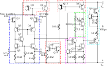
An operational amplifier is a circuit of about 22 transistors organized with the goal of producing an amplifier.

Ideally the open loop gain (AOL) is infinite. In reality the output will "rail" to either the positive or negative supply.
Open loop means that there are no devices connecting the output to the inverting input (- or negative input). In practice most op-amps are used in "closed-loop", "negative feedback" configuration. Closed loop designs (in the first approximation) require remembering two "golden rules":
- I. The output attempts to do whatever is necessary to make the voltage difference between the inputs zero.
- II. The inputs draw no current.
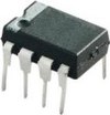
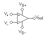
| Op-amp | Pins | Symbol |
|---|---|---|
 |
 |

|
Subtraction
editUnder the condition that the Rf /R1 = Rg /R2, the output expression becomes:
"A" is the differential gain of the circuit.
Operating Point
editOp Amps are balanced:
- The supplies are +V and -V, not V_s and ground. This is why many power supplies have both +15 and -15 volts or +5 and -5 volts.
- They are made with almost equal numbers of PNP and NPN transistors.
- They are best operated where the output is around 0 volts.
Don't try to fit them into a digital circuit.
Typical Applications
editOp Amps are typically used to amplify.
Vacuum tubes (light bulbs with a grid and three wires) (1907 by Lee De Forest) solved the existing need for amplification of a weak data signal. But vaccuum tubes broke in less than a year. Many famous scientist/engineer's first experience with technology was radio repair including Feynman and Armstrong.
Transistors came next in 1951 created by Shockley. They enabled the transistor radio ... that could be held in the palm of one's hand. Transistors replaced vacuum tubes in almost all devices.
Operational Amplifiers emerged out of math, not inventor work shops. They emerged from the needs that MatLab fills today, not a simple calculator. Attempts were made to build them with vaccum tubes and every known transistor. The 741 op amp took until transistors matured .. 1968. The 741 is still in production. Op amps are found where the difference between two devices sensing the environment are needed. They are used to replace inductors in circuits because they are cheaper and lighter.
Inverting or Not?
editOp amps are drawn with the non-inverting input on top if the design goal is an output that same polarity as the input. Why isn't it just called "positive input"? Why isn't positive always on top?
The reason is that most op amps involve negative feedback. Most designs require circuitry to be connected to the "inverting" input. If possible the "non-inverting" input is grounded. This means that the sweet middle operating point is more plausible.
But the most important reason comes from multiple op amp designs. The negative or positive nature of the output can be more easily seen if the inverting and non-inverting inputs flip based upon the immediate output design intention. Negative output means that eventually a final op amp may be needed to flip the output positive.
Local Feedback
editOp amp circuits are easy to design as long as the feedback is kept local ... meaning the feedback loops back over only one local op amp. The feedback does not span outputs. Only outputs connected to inputs connect two op amps.
Buffer
editBuffers are needed to re-invigorate a signal. Fanout is when an output is connected to too many inputs. Buffers can restore the power needed to drive the rest of the circuit.
Adder
editA adder sums several (weighted) voltages:
When , and independent
When
Integrator
edit(where and are functions of time, is the output voltage of the integrator at time t = 0.)
There are several potential problems with this circuit.
- It is usually assumed that the input has zero DC component (i.e., has a zero average value). Otherwise, unless the capacitor is periodically discharged, the output will drift outside of the operational amplifier's operating range.
- Even when has no offset, the leakage or bias currents into the operational amplifier inputs can add an unexpected offset voltage to that causes the output to drift. Balancing input currents and replacing the non-inverting ( ) short-circuit to ground with a resistor with resistance can reduce the severity of this problem.
- Because this circuit provides no DC feedback (i.e., the capacitor appears like an open circuit to signals with ), the offset of the output may not agree with expectations (i.e., may be out of the designer's control with the present circuit).
- The initial voltage is typically enforced by a power supply in parallel with the capacitor that is switched out of the circuit at t=0.
Many of these problems can be made less severe by adding a large resistor in parallel with the feedback capacitor. At significantly high frequencies, this resistor will have negligible effect. However, at low frequencies where there are drift and offset problems, the resistor provides the necessary feedback to hold the output steady at the correct value. In effect, this resistor reduces the DC gain of the "integrator" – it goes from infinite to some finite value .
Differentiator
editThis circuit differentiates the (inverted) signal over time.
Inductor Replacement
editSimulates an inductor. The circuit exploits the fact that the current flowing through a capacitor behaves through time as the voltage across an inductor. The capacitor used in this circuit is smaller than the inductor it simulates and its capacitance is less subject to changes in value due to environmental changes.
This circuit is unsuitable for applications relying on the input impedance seen left to right and indicated by the red symbol is the same in both circuits. The output on the left could tell the difference between the op amp circuit and an inductor.
Of course there would not be a magnetic field (for a motor or transformer) and any application relying on back EMF would not work.
