Descriptive Geometry/Complex Solid Intersections
Cylinders edit
Line Intersecting a solid Find piercing points by using sectional views.
1. Think of the given line in one view to be the edge view of a section of the given solid. 2. The points where the line crosses the base of the cylinder in this view are the piercing points. 3. Find the piercing points in the other view by projecting these points down until they cross the given line.
Line Intersecting a cylinder
Use a vertical section plane.
1. In the top view, consider the given line to be the edge view of a vertical section plane. 2. Locate the points where the line crosses the base. Project theses piercing points down to the front view. 3. The piercing points are where theses points intersect the line in the front view.
Line Intersecting an inclined cylinder
Create a section plane parallel to the axis of the cylinder.
1. In front view, select two points on the given line and draw two lines that are parallel to the axis through these points. 2. Mark the points at which these two lines intersect the edge view of the base of the cylinder. Project these points to the top view until they hit the base. 3. Draw lines parallel to the axis, to the other base of the cylinder. 4. Where these two lines intersect the given line are the two piercing points.
Plane Intersecting a Cylinder
A cylinder is made of infinite number of lines that are parallel to the axis, along the base. Create a convenient cutting plane in one view, that contains a piercing point and project it to find the trace and to locate the piercing point in the other view.
1. In top view, locate the apparent piercing points, where each side of the given plane crosses the base of the cylinder. 2. Project these piercing points to the front view and mark them where they meet the same side of the plane. 3. To find more points that make up the plane of intersection, use cutting planes and traces: a. Pick a point on the base in top view (should lie inside the given plane and along the base of the cylinder). b. Draw a line (represents the edge view of the cutting plane) that contains that point, across the given plane. c. Project the line and the piercing point down to the front view. The piercing point (in the front view) is located on that line. d. Connect these piercing points (in the front view), taking visibility into consideration, to find the plane of intersection.
For example, questions, see files "Problem 1 Line Intersecting Cylinder" and "Problem 2 Plane Intersecting Cylinder."
-
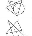
 Problem1 Line Intersecting Cylinder
 -
 Problem 1 Solution


-
 Problem2 Plane Intersecting Cylinder
 -
 Problem 2 Solution


Cones edit
Intersection between plane and cone (given two views)
Draw line parallel to folding line in one view through one point of intersecting plane. Transfer line to other given view with points on respective lines to get line in true length. Draw folding line perpendicular to true length line and transfer points of cone to auxiliary view. Transfer intersecting plane to auxiliary view to show plane in edge view and treat it as a cutting plane. Draw lines from edge view of base plane to the vertex of the cone. Transfer lines to both other views. Find intersections between cutting plane and cone line in auxiliary view and transfer points back to other two views to find intersections. Determine visibility.
-
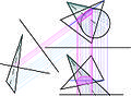
 Problem 1
 -
 Problem 1 - Select arbitrary points on intersecting line
 -
 Problem 1 - Extend lines from vertex
 -
 Problem 1 - Find piercing points


Intersection between line and cone (given two views)
Choose two arbitrary points on the intersecting line in front view. Draw lines through these two points from the vertex to intersect the edge view of the base plane of the cone, label these intersections. Project two arbitrary points on line vertically to top view onto intersecting line and draw lines through these points from the vertex in top view. Project the two labelled intersections to top view and mark where it intersects the previously drawn lines from the vertex through the two projected arbitrary points. Connect these two points to create the cutting plane of the base plane. Connect where this line intersects the base of the cone in top view to the vertex, where these two lines crosses the intersecting line are the piercing points of the line. Carry the piercing points back to front view.
-
 Problem 2
 -
 Problem 2 - Find one line in true length
 -
 Problem 2 - Create edge view of intersecting plane from true length line
 -
 Problem 2 - Extend lines from vertex of cone
 -
 Problem 2 - Find intersections


Spheres edit
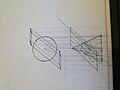
Section of a sphere:
Given two views of a sphere and its section. (Fig1.1)

To find the true section of the sphere, we draw an auxiliary view.
The folding line for this view must be parallel to the line (edge view of section shown in other view).(fig1.2)

This will give us the true size of the section of the sphere. The auxiliary view is constructed by simply transferring distances. (Fig1.3)

Intersection of a line and a sphere: (Fig2.1)

We can use the above construction to figure out the piercing points of a line and a sphere. To do so, we assume that the line in one of the two views is the edge view of the cutting plane (section plane). (Fig2.2)

Using this information, we can construct the corresponding section of the sphere in the other view. The points where the line intersects this section can be transferred back onto the line to find the piercing points of the line and the sphere. We can project these back to the first view.(Fig2.3)

Practice problems: (with solutions) (Refer to pictures named: Problem 1. Find (a)true section of the sphere and (b) piercing points Solution 1(a) Solution 1(b) Problem 2 Solution 2 (a&b)
true_section_of_the_sphere_and_(b)_piercing_points.jpg)
.jpg)
.jpg)
true_section_of_the_sphere_and_(b)_piercing_points_of_the_plane.jpg)
.jpg)
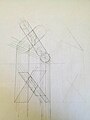
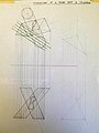
Intersections between Complex Solids edit
Intersection between Complex Solids with Complex Solids Cylinder and Cylinder Cone and Cylinder First determine if the two complex solids have axis that are parallel to each other. If not, the first step is to construct a plane that contains a line that is parallel to the axis of both the complex solids which intersects each solid in top view. If the faces of the shapes are not coplanar, extend one in front view until they have a common base plane. Construct cutting planes that intersect the bases of the two solids parallel to the previously constructed plane to determine the intersections between the planes and the solids as shown in figure Project the intersecting points obtained in the second step onto the corresponding solid in the other view. Using those points of intersection, construct lines parallel to the axis of that solid so it intersects the solids in the same view that you used for the step above. Mark the intersections that are generated from the same cutting plane. The two complex solids intersect at these points. Join the intersecting points to get the shape where the two solids intersect each other. Project the above obtained points corresponding to the solids in the other view to obtain the shape of the intersecting plane. Note: You should use a good number of intersecting planes and follow the steps above to obtain an accurate shape of intersection.
To understand this topic better do the practice problems assigned below.
-
 Descriptive Geometry
 -
 Descriptive Geometry
 -
 Descriptive Geometry
 -
 Descriptive Geometry
 -
 Image for Question 1 on Intersection of Complex Solids
 -
 Answer for Question 1 on Intersection of Complex Solids
 -
 Image for Question 2 on Intersection of Complex Solids
 -
 Answer for Question 2 on Intersection of Complex Solids


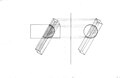
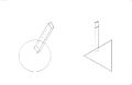
Intersections with Complex and Planar Solids edit
Break the planar solid into individual surfaces and address each surface individually. For each surface on the planar solid, find intersections between the surface and the complex solid. (Top View) Using piercing points project these intersections into front view. These will be the points where the two solids intersect. (Top/Front View) If more points are needed to complete the shape of the intersection, create lines on each surface and using the same method as before find more points of intersection. Repeat with the other surfaces on the planar solid until a complete shape of intersection is found.
-
 Example Problem 1
 -
 Example Problem 1 Solution
 -
 Example Problem 2
 -
 Example Problem 2 Solution
 -
 Setup
Setup -
 Solution
 -
 Setup
Setup -
 Solution


