Circuit Theory/Active Filters
Active filters have op amps or amplifiers in them. They usually don't have inductors because they are expensive, heavy and large when compared to capacitors.
Minimal Filter Transfer Functions edit
Each filter type has a characteristic transfer function:
| Filter Type | Transfer Function |
|---|---|
| High Pass | |
| Low Pass | |
| Band Pass | |
| Notch |


First the goal is to build a transfer function from the op-amp circuit so that a bode diagram can be plotted. This is a simple matter of substituting s for derivatives in the terminal relations.
Active Filter Components edit
Rather than draw an example op amp circuit for each of the above filters, it is easier to draw four op amp circuits that are more related to the desired transfer function:
| Circuit | Generates | Transfer Function |
|---|---|---|
 |
Complex Pole | derivation |
 |
Zero at Origin | |
 |
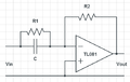
Real Pole | |
 |
Real Zero |


Most filter design starts with the desired transfer function. Then the circuit is built. With the above four configurations, any transfer function can be created.
Better filters are have stepper slopes and narrower bands in their bode diagrams. This is measured with a factor called Q for quality. This is why there are so many different types of filter designs.
Under Constrained Design edit
Suppose you wanted this transfer function:

Then an active filter could be built like this:
-
 stage A
-
 stage B
-
stage C
-
stage D
Choosing values to match the above transfer function results in a table like this:
| Input Stage Variables | Feedback stage variables |
|---|---|


There are 12 unknowns and 8 equations. This is called an under constrained problem. It means that one can apply other design rules. For example, capacitors are more expensive than resistors. Buying in bulk is less expensive. So ... choose one value for all the capacitors and then adjust resistor values. Choose C = 1μF Then all the resistors are 1 M&Ohm; accept R1B, R1C and R1D.